
Videos
Solve Prob. 5.85, assuming that the cross section of the beam is inverted, with the flange of the beam resting on the supports at B and C.
5.85 Determine the largest permissible distributed load w for the beam shown, knowing that the allowable normal stress is +80 MPa in tension and –130 MPa in compression.
Fig. P5.85
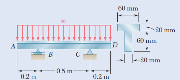
The largest permissible distributed load w.
Answer to Problem 86P
The largest permissible distributed load (w) is
Explanation of Solution
Given information:
The allowable normal stress of the material in tension is
The allowable normal stress of the material in compression is
Calculation:
Show the free-body diagram of the beam as in Figure 1.
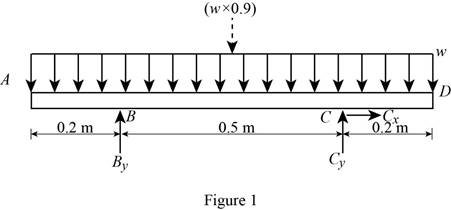
Determine the vertical reaction at point C by taking moment about point B.
Determine the vertical reaction at point B by resolving the vertical component of forces.
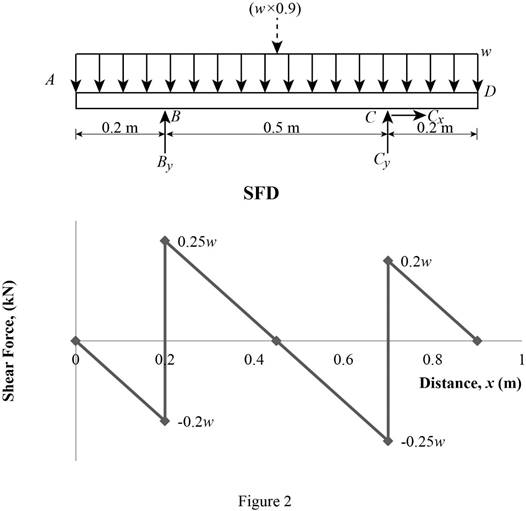
Shear force:
Show the calculation of shear force as follows;
Show the calculated shear force values as in Table 1.
| Location (x) m | Shear force (V) kN |
| A | 0 |
| B (Left) | –0.2w |
| B (Right) | 0.25w |
| C (Left) | –0.25w |
| C (Right) | 0.2w |
| D | 0 |
Plot the shear force diagram as in Figure 2.
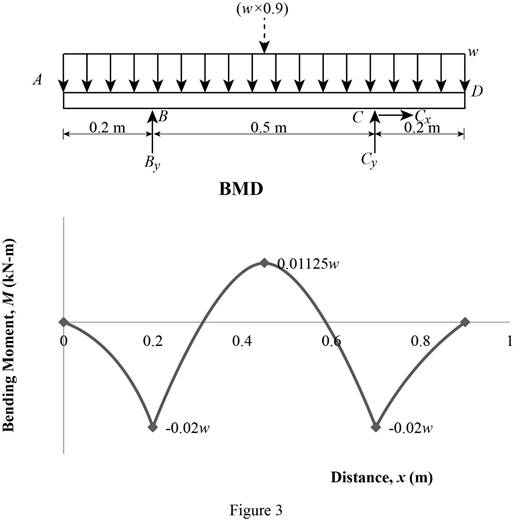
Location of the maximum bending moment:
The maximum bending moment occurs where the shear force changes sign.
Refer to Figure 2;
Use the similar triangle concept.
The maximum bending moment occurs at a distance of 0.45 m from left end of the beam.
Bending moment:
Show the calculation of the bending moment as follows;
Show the calculated bending moment values as in Table 2.
| Location (x) m | Bending moment (M) kN-m |
| A | 0 |
| B | –0.02w |
| Max BM | 0.01125w |
| C | –0.02w |
| D | 0 |
Plot the bending moment diagram as in Figure 3.
Show the free-body diagram of the T-section as in Figure 4.
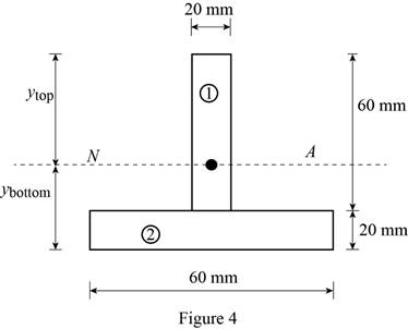
Determine the centroid in y-axis
Here, the area of the section 1 is
Refer to Figure 4;
Substitute
Determine the moment of inertia (I) using the equation.
Here, the depth of the section 1 is
Substitute 60 mm for
Refer to Figure 4;
Tension at Points B and C:
Refer to Figure 3;
Determine the distributed load (w) using the relation.
Substitute –0.02w for
Compression at Points B and C:
Refer to Figure 3;
Determine the distributed load (w) using the relation.
Substitute –0.02w for
Tension at Points E:
Refer to Figure 3;
Determine the distributed load (w) using the relation.
Substitute 0.01125w for
Compression at Points E:
Refer to Figure 3;
Determine the distributed load (w) using the relation.
Substitute 0.01125w for
Refer to the calculated distribution loads; the smallest value controls the design.
Therefore, the largest permissible distributed load (w) is
Want to see more full solutions like this?
Chapter 5 Solutions
Mechanics of Materials, 7th Edition


- My ID#016948724 please solve this problems and show me every step clear to follow pleasearrow_forwardMy ID# 016948724arrow_forwardPlease do not use any AI tools to solve this question. I need a fully manual, step-by-step solution with clear explanations, as if it were done by a human tutor. No AI-generated responses, please.arrow_forward
- Please do not use any AI tools to solve this question. I need a fully manual, step-by-step solution with clear explanations, as if it were done by a human tutor. No AI-generated responses, please.arrow_forwardPlease do not use any AI tools to solve this question. I need a fully manual, step-by-step solution with clear explanations, as if it were done by a human tutor. No AI-generated responses, please.arrow_forward[Q2]: The cost information supplied by the cost accountant is as follows:Sales 20,00 units, $ 10 per unitCalculate the (a/ newsale guantity and (b) new selling price to earn the sameVariable cost $ 6 per unit, Fixed Cost $ 30,000, Profit $ 50,000profit ifi) Variable cost increases by $ 2 per unitil) Fixed cost increase by $ 10,000Ili) Variable cost increase by $ 1 per unit and fixed cost reduces by $ 10,000arrow_forward
- can you please help me perform Visual Inspection and Fractography of the attatched image: Preliminary examination to identify the fracture origin, suspected fatigue striation, and corrosion evidences.arrow_forwardcan you please help[ me conduct Causal Analysis (FTA) on the scenario attatched: FTA diagram which is a fault tree analysis diagram will be used to gain an overview of the entire path of failure from root cause to the top event (i.e., the swing’s detachment) and to identify interactions between misuse, material decay and inspection errors.arrow_forwardhi can you please help me in finding the stress intensity factor using a k-calcluator for the scenario attathced in the images.arrow_forward
 Elements Of ElectromagneticsMechanical EngineeringISBN:9780190698614Author:Sadiku, Matthew N. O.Publisher:Oxford University Press
 Mechanics of Materials (10th Edition)Mechanical EngineeringISBN:9780134319650Author:Russell C. HibbelerPublisher:PEARSON
 Thermodynamics: An Engineering ApproachMechanical EngineeringISBN:9781259822674Author:Yunus A. Cengel Dr., Michael A. BolesPublisher:McGraw-Hill Education
 Control Systems EngineeringMechanical EngineeringISBN:9781118170519Author:Norman S. NisePublisher:WILEY
 Mechanics of Materials (MindTap Course List)Mechanical EngineeringISBN:9781337093347Author:Barry J. Goodno, James M. GerePublisher:Cengage Learning
 Engineering Mechanics: StaticsMechanical EngineeringISBN:9781118807330Author:James L. Meriam, L. G. Kraige, J. N. BoltonPublisher:WILEY