
Basic Engineering Circuit Analysis
11th Edition
ISBN: 9781118539293
Author: J. David Irwin, R. Mark Nelms
Publisher: WILEY
expand_more
expand_more
format_list_bulleted
Concept explainers
Videos
Textbook Question
Chapter 5, Problem 5PFE.2TP
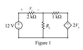
Find the value of the load
a. 22.5 mW c. 64.3 mW
b. 80.4 mW d. 121.5 mW
Expert Solution & Answer
Want to see the full answer?
Check out a sample textbook solution
Students have asked these similar questions
2. Suppose the Laplace transform of a causal signal x(t) is given by
s² +2
X(s) =
S³ + 1
Using the lookup tables for standard Laplace transforms and the Laplace transform
properties, find the Laplace transforms of the following signals. You do not need to
simplify the expressions.
a) x₁(t) = e² x(t) + 38(t − 1) − (t − 2)² u(t − 2)
b) x2(t) = x(2t - 1) + et u(t − 2)
Please explain in detail the steps to solve this. Thank you
6. Answer the following questions. Take help from ChatGPT to answer these questions
(if you need). But write the answers briefly using your own words with no more than
two sentences and make sure you check whether ChatGPT is giving you the
appropriate answers in our context.
a) What is the difference between a regulator and a servo system? Which is harder
to build?
b) What are the advantages and drawbacks of manual control systems over
automatic ones?
c) Does transfer exist for the non-linear systems?
d) Explain the convolution property of the Laplace transform.
e) What are the advantages of using state-space representation?
Chapter 5 Solutions
Basic Engineering Circuit Analysis
Ch. 5 - Find Io in the network in Fig. P5.1 using...Ch. 5 - Find Io in the network in Fig. P5.2 using...Ch. 5 - Find Io in the network in Fig. P5.3 using...Ch. 5 - Find Vo in the network in Fig. P5.4 using...Ch. 5 - Find Io in the circuit in Fig. P5.5 using...Ch. 5 - Find Io in the network in Fig. P5.6 using...Ch. 5 - Find Io in the circuit in Fig. P5.7 using...Ch. 5 - Find Vo in the network in Fig. P5.8 using...Ch. 5 - Find Vo in the network in Fig. P5.9 using...Ch. 5 - In the network in Fig. P5.l0, find using...
Ch. 5 - Find Io in the network in Fig. P5.11 using...Ch. 5 - Find Io in the network in Fig. P5.12 using...Ch. 5 - Find IA in the network in Fig. P5.13 using...Ch. 5 - Using superposition, find IA in the circuit in...Ch. 5 - Find IA in the network in Fig. P5.15 using...Ch. 5 - Using superposition, find Vo in the network in...Ch. 5 - Use superposition to find Io in the circuit in...Ch. 5 - Use superposition to find Io in the network in...Ch. 5 - Use superposition to find Vo in the circuit in...Ch. 5 - Find Vo in the circuit in Fig. P5.20 using...Ch. 5 - Find Io in the circuit in Fig. P5.21 using...Ch. 5 - Use superposition to find Io in the circuit in...Ch. 5 - Use superposition to find Io in the network in...Ch. 5 - Use superposition to find Io in the circuit in...Ch. 5 - Use Thévenins theorem to find Vo in the network...Ch. 5 - Use Thévenins theorem to find in the network in...Ch. 5 - Use Thévenins theorem to find Vo in the network...Ch. 5 - Find Io in the network in Fig. P5.28 using...Ch. 5 - Find Vo in the network in Fig. P5.28 using...Ch. 5 - Use Thévenins theorem to find 10 in the network...Ch. 5 - Find Vo in the network in Fig. P5.31 using...Ch. 5 - Find Io in the circuit in Fig. P5.32 using...Ch. 5 - Find Io in the network in Fig. P5.33 using...Ch. 5 - Find Io in the network in Fig. P5.34 using...Ch. 5 - Find Io in the circuit in Fig. P5.35 using...Ch. 5 - Find Io in the network in Fig. P5.36 using...Ch. 5 - Using Thévenins theorem, find IA in the circuit...Ch. 5 - Find Vo in the network in Fig. P5.38 using...Ch. 5 - Find Vo in the circuit in Fig. P5.39 using...Ch. 5 - Find Io in the circuit in Fig. P5.40 using...Ch. 5 - Find Vo in the network in Fig. P5.41 using...Ch. 5 - Find Io in the network in Fig. P5.42 using...Ch. 5 - Find Vo in Fig. P5.43 using Thévenins theorem.Ch. 5 - Use Thévenins theorem to find Vo in the circuit...Ch. 5 - Use Thévenins theorem to find Io in Fig. P5.45.Ch. 5 - Find Vo in the network in Fig. P5.46 using...Ch. 5 - Use Thévenins theorem to find Io in the network...Ch. 5 - Use Thévenins theorem to find Io in the circuit...Ch. 5 - Given the linear circuit in Fig. P5.49, it is...Ch. 5 - If an 8-k load is connected to the terminals of...Ch. 5 - Use Nortons theorem to find Io in the circuit in...Ch. 5 - Find Io in the network in Fig. P5.52 using Nortons...Ch. 5 - Use Nortons theorem to find Io in the circuit in...Ch. 5 - Use Nortons theorem to find Vo in the network in...Ch. 5 - Find Io in the network in Fig. P5.55 using Nortons...Ch. 5 - Use Nortons theorem to find Vo in the network in...Ch. 5 - Find Vo in the network in Fig. P5.57 using Nortons...Ch. 5 - Use Nortons theorem to find Io in the circuit in...Ch. 5 - Find Vo in the circuit in Fig. P5.59 using Nortons...Ch. 5 - Use Nortons theorem to find Io in the network in...Ch. 5 - Use Nortons theorem to find Io in the circuit in...Ch. 5 - In the network in Fig. P5.62, find Vo using...Ch. 5 - Use Thévenins theorem to find 10 in the circuit...Ch. 5 - Find Vo in the network in Fig. P5.64 using...Ch. 5 - Use Thévenins theorem to find Vo in the circuit...Ch. 5 - Find Io in the circuit in Fig. P5.66 using...Ch. 5 - Use Thévenins theorem to find Io in the circuit...Ch. 5 - Use Thévenins theorem to find Vo in the circuit...Ch. 5 - Find Vo in the network in Fig. P5.69 using...Ch. 5 - Use Nortons theorem to find Vo in the network in...Ch. 5 - Find Vo in the circuit in Fig. P5.71 using...Ch. 5 - Find Vo in the network in Fig. P5.72 using...Ch. 5 - Find Vo in the network in Fig. P5.73 using Nortons...Ch. 5 - Use Thévenins theorem to find the power supplied...Ch. 5 - Find Vo in the circuit in Fig. P5.75 using...Ch. 5 - Find Vo in the network in Fig. P5.76 using...Ch. 5 - Find Vo in the network in Fig. P5.77 using...Ch. 5 - Use Thévenins theorem to find I2 in the circuit...Ch. 5 - Use Thévenins theorem to find Vo in the circuit...Ch. 5 - Use Thévenins theorem to find Vo in the circuit...Ch. 5 - Use Thévenins theorem to find Io in the network...Ch. 5 - Use Thévenins theorem to find Vo in the network...Ch. 5 - Find the Thévenin equivalent of the network in...Ch. 5 - Find the Thévenin equivalent of the network in...Ch. 5 - Find the Thévenin equivalent of the circuit in...Ch. 5 - Find the Thévenin equivalent of the network in...Ch. 5 - Find the Thévenin equivalent circuit of the...Ch. 5 - Find Vo in the network in Fig. P5.88 using source...Ch. 5 - Find Io in the network in Fig. P5.89 using source...Ch. 5 - Use source transformation to find Vo in the...Ch. 5 - Find 10 in the network in Fig. P5.91 using source...Ch. 5 - Find Vo in the network in Fig. P5.92 using source...Ch. 5 - Use source transformation to find Io in the...Ch. 5 - Find the Thévenin equivalent circuit of the...Ch. 5 - Find Io in the circuit in Fig. P5.95 using source...Ch. 5 - Find Io in the network in Fig. P5.96 using source...Ch. 5 - Find Io in the network in Fig. P5.97 using source...Ch. 5 - Find Vo in the network in Fig. P5.98 using source...Ch. 5 - Find Io in the network in Fig. P5.99 using source...Ch. 5 - Find in the circuit in Fig. P5.100 using source...Ch. 5 - Use source transformation to find Io in the...Ch. 5 - Using source transformation, find Vo in the...Ch. 5 - Use source transformation to find Io in the...Ch. 5 - Use source transformation to find Io in the...Ch. 5 - Use source transformation to find 10 in the...Ch. 5 - Using source transformation, find 10 in the...Ch. 5 - Use source exchange to find Io in the network in...Ch. 5 - Use a combination of Y- transformation and source...Ch. 5 - Use source exchange to find Io in the circuit in...Ch. 5 - Use source exchange to find Io in the network in...Ch. 5 - Use source exchange to find Io in the network in...Ch. 5 - Find RL in the network in Fig. P5.112 in order to...Ch. 5 - In the network in Fig. P5.113, find RL for maximum...Ch. 5 - Find RL for maximum power transfer and the maximum...Ch. 5 - Find RL for maximum power transfer and the maximum...Ch. 5 - Find RL for maximum power transfer and the maximum...Ch. 5 - Find RL for maximum power transfer and the maximum...Ch. 5 - Determine the value of RL in the network in Fig....Ch. 5 - Find RL for maximum power transfer and the maximum...Ch. 5 - Find the value of RL in the network in Fig. P5.120...Ch. 5 - Find the value of RL for maximum power transfer...Ch. 5 - Find the maximum power that can be transferred to...Ch. 5 - In the network in Fig. P5.123, find the value of...Ch. 5 - In the network in Fig. P5.124, find the value of...Ch. 5 - Find the value of RL in Fig. P5.125 for maximum...Ch. 5 - Calculate the maximum power that can be...Ch. 5 - Find RL for maximum power transfer and the maximum...Ch. 5 - Find the value of RL in Fig. P5.128 for maximum...Ch. 5 - A cell phone antenna picks up a call. If the...Ch. 5 - Some young engineers at the local electrical...Ch. 5 - Determine the maximum power that can be delivered...Ch. 5 - Find the value of the load RL in the network in...Ch. 5 - Find the value of RL in the network in fig. 5PFE-3...Ch. 5 - What is the current I in Fig. 5PFE4? a. 8 Ac. 0 A...Ch. 5 - What is the open-circuit voltage Voc at terminals...
Additional Engineering Textbook Solutions
Find more solutions based on key concepts
Give a general description of the input validation process.
Starting Out with Programming Logic and Design (5th Edition) (What's New in Computer Science)
ICA 8-18
You have been working to develop a new fictitious compound in the lab. Determine the amount in units o...
Thinking Like an Engineer: An Active Learning Approach (4th Edition)
In each case, express the shear and moment functions In terms of x, and then draw the shear and moment diagrams...
Mechanics of Materials (10th Edition)
Determine the force in each member of the truss, and state if the members are in tension or compression Set = ...
INTERNATIONAL EDITION---Engineering Mechanics: Statics, 14th edition (SI unit)
Write a statement that declares a List reference variable, instantiates an ArrayList object that can hold Strin...
Starting Out with Java: From Control Structures through Data Structures (4th Edition) (What's New in Computer Science)
In the following exercises, write a program to carry out the task. The program should use variables for each of...
Introduction To Programming Using Visual Basic (11th Edition)
Knowledge Booster


Learn more about
Need a deep-dive on the concept behind this application? Look no further. Learn more about this topic, electrical-engineering and related others by exploring similar questions and additional content below.Similar questions
- 4. Find the differential equation of the following system whose transfer function is given by S+3 H(s) = s3 +3s+2arrow_forwardPreliminary Laboratory (Prelab) Work Complete the following tasks in the space provided below for the circuit shown in Figure 2. 1. Use voltage division to compute the phasor voltages VR and Vc assuming nominal values of R = 1000[2], C = 0.01[u], and a cosinusoidal time-domain source voltage signal given by equation 5 below. Voltage division must be used to receive any credit. (10 points) equation (5) Vs(t) = VRMSCOS(ct + 0) = 5cos(@t + 0) = 5cos(62832t + 0) = 5cos(62832t) [V] =VRMSCOS(2лft + 0) = 5cos[2л(10000)t + 0] = 5cos[2л(10000)t] [V] 2. Compute the phasor current, Is. (3 points) 3. Calculate the complex power, S, active power, P, and reactive power, Q, for the circuit. (4 points) 4. Construct the phasor diagram for the circuit, and show mathematically that the phasor (vector) sum of the phasor voltages VR and Vc is equal to Vs. (3 points) Agilent 33210A (BECC4242) or Vs Keysight 33500B (BECC4261) Function Generators Is R w + VR Vc + + Zc V out =Vc Figure 2: RC circuit connected…arrow_forwardPlease explain in detail. My answer for the first question is 15/2. I am more confused about how to do the graphing part and figure how long it will take to reach its final value. Thank you, I will like this.arrow_forward
- This is the 3rd time i'm asking this. SOLVE THIS AND FIND V0 , the last answer i was given is -2V which is not even one of the listed options. the listed options are: 12V,4V,24V,6V. first answer given to me was 4V but after i simulated on ltspice albeit i'm not sure if i simulated correct i got a different answer and when i solved it myself i got a different answer. this is my last remaining question. PLEASE SOLVE CORRECTLY AND PROPERLY. NODAL ANALYSIS IS BEST TO USE HERE. IT IS AN IDEAL OP-AMP. SIMULATE USING LTSPICE AND GIVE ME FINAL ANSWER IF POSSIBLE AS THAT IS ALL I CARE ABOUT NOT THE PROCESS. THANK YOU. WILL UPVOTE CORRECT ANSWER, but downvote wrong answer.arrow_forwardFind the exact value of V0. This question was already asked here and the answer was 4V i solved it myself and got a different answer and when i simulated it i also got a different answer.But i might be wrong. so please solve this for me and IF POSSIBLE simulate it so we can be 100% sure that the answer is correct as it's very important that i understand where i went wrong.arrow_forwardFind load flow Solution 1.2 20 Z12 = 0.01+jo.03 in Z₁4=0.02+0.04 и а 9.01+10.03 0.02+0.04 0.01+0.03 58-1 Vek 1.05 100 MVA Pe=230 MW 150 MW w 140 MW 01012 +0.035 80 M√ar 723=0.01+0.03 90 mvare Z34 = 0.012+ 10.035arrow_forward
- SD = 100 MVA 1.12° 150mw ← 0.01+0.03 10.02 -0.04 Too M P = 250 MW 0.02+0.04 0.012 jo.03 $ (V3)=1.05 P.4 -03 = = 200 MW 212=0.01+10.03 Zzze 0.02 +10.04 214=0.02+10.04 Z34 = 0.012+10.03arrow_forwardChoose the correct answer to the following questions: 1- What is the total power radiated in Watts for the power density W = a) 4π² b) 8m²/3 2- Fresnel zone is also called as sine W/m²? 3r² c) 4π²/3 d) 2π²/3 a) Near Field b) Far Field c) Electrostatic Field d) Reactive Field 3- The far-field distance at 900 MHz, if the maximum antenna dimension is 0.75 m is.... a) 3.375 m b) 3.5m c) 3.375 cm d) none 4- The antenna gain is on input power to antenna and on power due to ohmic losses. c) Independent, dependent d) a) Independent, independent b) Dependent, independent Dependent, dependent 5- If beam width of the antenna increases, then directivity. a) Decreases b) Increases c) Remains unchanged d) Depends on type of antennaarrow_forwardplease solve this and clarify each step. thanksarrow_forward
- The input reactance of 1/2 dipole with radius of 1/30 is given as shown in figure below, Assuming the wire of dipole is conductor 5.6*107 S/m, determine at f=1 GHz the a- Loss resistance, b- Radiation efficiency c- Reflection efficiency when the antenna is connected to T.L shown in the figure. Rr Ro= 50 2 Avg/4 RL -j100 [In(l/a) 1.5] tan(ẞ1)arrow_forwardFind Zeq here. i already had one solution written to me but it's wrong. my main question is. i know that i do the parallel connection first so 2x2 / 2+2 = 1ohm but what i'm asking is since it's an open terminal is R3,2(parallel resistors) in series to R1? or should i first do R3,2 // to ZL and then add R1 in series? PLEASE READ THIS. and solve properly. EXPLAIN WHAT I ASKED PROPERLY. UPVOTE WILL BE GIVEN.arrow_forwardThe E-field pattern of an antenna, independent of o, varies as follows: E = 0 7100 0° ≤0≤45° 45° < 0 ≤ 90° 90° < 0 ≤ 180° (a) What is the directivity of this antenna? (b) What is the radiation resistance of the antenna at 200 m from it if the field is equal to 10 V/m (rms) for 0 = 0° at that distance and the terminal current is 5 A (rms)?arrow_forward
arrow_back_ios
SEE MORE QUESTIONS
arrow_forward_ios
Recommended textbooks for you
 Introductory Circuit Analysis (13th Edition)Electrical EngineeringISBN:9780133923605Author:Robert L. BoylestadPublisher:PEARSON
 Delmar's Standard Textbook Of ElectricityElectrical EngineeringISBN:9781337900348Author:Stephen L. HermanPublisher:Cengage Learning
 Programmable Logic ControllersElectrical EngineeringISBN:9780073373843Author:Frank D. PetruzellaPublisher:McGraw-Hill Education
 Fundamentals of Electric CircuitsElectrical EngineeringISBN:9780078028229Author:Charles K Alexander, Matthew SadikuPublisher:McGraw-Hill Education
 Electric Circuits. (11th Edition)Electrical EngineeringISBN:9780134746968Author:James W. Nilsson, Susan RiedelPublisher:PEARSON
 Engineering ElectromagneticsElectrical EngineeringISBN:9780078028151Author:Hayt, William H. (william Hart), Jr, BUCK, John A.Publisher:Mcgraw-hill Education,
Introductory Circuit Analysis (13th Edition)
Electrical Engineering
ISBN:9780133923605
Author:Robert L. Boylestad
Publisher:PEARSON
Delmar's Standard Textbook Of Electricity
Electrical Engineering
ISBN:9781337900348
Author:Stephen L. Herman
Publisher:Cengage Learning
Programmable Logic Controllers
Electrical Engineering
ISBN:9780073373843
Author:Frank D. Petruzella
Publisher:McGraw-Hill Education
Fundamentals of Electric Circuits
Electrical Engineering
ISBN:9780078028229
Author:Charles K Alexander, Matthew Sadiku
Publisher:McGraw-Hill Education
Electric Circuits. (11th Edition)
Electrical Engineering
ISBN:9780134746968
Author:James W. Nilsson, Susan Riedel
Publisher:PEARSON
Engineering Electromagnetics
Electrical Engineering
ISBN:9780078028151
Author:Hayt, William H. (william Hart), Jr, BUCK, John A.
Publisher:Mcgraw-hill Education,
Current Divider Rule; Author: Neso Academy;https://www.youtube.com/watch?v=hRU1mKWUehY;License: Standard YouTube License, CC-BY