
Concept explainers
Videos
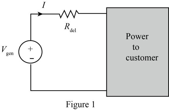
Some young engineers at the local electrical utility are debating ways to lower operating costs. They know that if they can reduce losses, they can lower operating costs. The question is whether they should design for maximum power transfer or maximum efficiency, where efficiency is defined as the ratio of customer power to power generated. Use the model in Fig. P5.130 to analyze this issue and justify your conclusions. Assume that both the generated voltage and the customer load are constant.
Want to see the full answer?
Check out a sample textbook solution
Chapter 5 Solutions
Basic Engineering Circuit Analysis
Additional Engineering Textbook Solutions
Starting Out with C++: Early Objects (9th Edition)
Web Development and Design Foundations with HTML5 (8th Edition)
Mechanics of Materials (10th Edition)
Electric Circuits. (11th Edition)
Management Information Systems: Managing The Digital Firm (16th Edition)
Starting Out With Visual Basic (8th Edition)


- Explain the advantages of three-phase supply for distribution purposes. (b) Assuming the relationship between the line and phase values of currents and voltages, show that the active power input to a three-phase balanced load is √3VI cos φ, where V and I are line quantities. (c) Three similar inductors, each of resistance 10 Ω and inductance 0.019 H, are delta-connected to a three-phase, 400 V, 50 Hz sinusoidal supply. Calcu late: the value of the line current; the power factor and the active power input to the circuit. ANS: 59.5 A, 0.858 lag, 35.5 kWarrow_forwardnot use ai pleasearrow_forwardA three-phase, 400 V, star-connected motor has an output of 50 kW, with an efficiency of 90 per cent and a power factor of 0.85. Calculate the line current. Sketch a phasor diagram showing the voltages and currents. If the motor windings were connected in mesh, what would be the correct voltage of a three phase supply suitable for the motor? ANS: 90.8 A, 240 Varrow_forward
- Don't use ai to answer I will report you answerarrow_forwardShow with the aid of a phasor diagram that for both star- and delta-connected balanced loads, the total active power is given by √3VI cos φ, where V and I are the line values of voltage and current respectively and φ is the angle between phase values of voltage and current. A balanced three-phase load consists of three coils, each of resistance 4 Ω and inductance 0.02 H. Determine the total active power when the coils are (a) star-connected, (b) delta-connected to a 400 V, three phase, 50 Hz supply. ANS:11.56 kW, 34.7 kWarrow_forwardThe load connected to a three-phase supply comprises three similar coils connected in star. The line currents are 25 A and the apparent and active power inputs are 20 kVA and 11 kW respectively. Find the line and phase voltages, reactive power input and the resistance and reactance of each coil. If the coils are now con nected in delta to the same three-phase supply, calculate the line currents and the active power taken. ANS : 462 V, 267 V, 16.7 kvar, 5.87 Ω, 8.92 Ω; 75 A, 33 kWarrow_forward
- A three-phase delta-connected load, each phase of which has an inductive reactance of 40 Ω and a resistance of 25 Ω, is fed from the secondary of a three-phase star-connected transformer which has a phase voltage of 230 V. Draw the circuit diagram of the system and calculate: (a) the current in each phase of the load; (b) the p.d. across each phase of the load; (c) the current in the transformer secondary windings; the total active power taken from the supply and its power factor.arrow_forwardDerive the numerical relationship between the line and phase currents for a balanced three-phase delta connected load. Three coils are connected in delta to a three-phase, three-wire, 400 V, 50 Hz supply and take a line current of 5 A 0.8 power factor lagging. Calculate the resistance and inductance of the coils. If the coils are star-connected to the same supply, calculate the line current and the total power. Calculate the line cur rents if one coil becomes open-circuited when the coils are connected in star. Ans: 110.7 Ω, 0.264 H; 1.67 A, 926 W; 1.445 A, 1.445 A, 0arrow_forwardDerive, for both star- and delta-connected systems, an expression for the total power input for a balanced three-phase load in terms of line voltage, line current and power factor. The star-connected secondary of a transformer supplies a delta-connected motor taking a power of 90 kW at a lagging power factor of 0.9. If the volt age between lines is 600 V, calculate the current in the transformer winding and in the motor winding. Draw circuit and phasor diagrams, properly labelled, showing all voltages and currents in the transformer secondary and the motor. ANS: . 96.2 A, 55.6 Aarrow_forward
- Deduce the relationship between the phase and the line voltages of a three-phase star-connected generator. If the phase voltage of a three-phase star-connected generator is 200 V, what will be the line voltages: (a) when the phases are correctly connected; (b) when the connections to one of the phases are reversed? ans: 346 V; 346 V, 200 V, 200 Varrow_forwardQ2: Given a discrete sequence x(n) = [1,-1,2,4, 1, 3,-1,1] and its spectrum X(k): i. Show that: X(k) =G(k)+WH(k) k=0,1,2,3,4,5,6,7 where G(k) = DFT[g(n)] and H(k) = DFT[h(n)], g(n) and h(n) are even and odd components of x(n) respectively. ii. Compute G(k) and H(k) using the method of computation of DFTS of two real sequences. (15 marks)arrow_forwardQ2: Given a discrete sequence x(n) = [1,-1,2,4, 1, 3,-1,1] and its spectrum X(k): i. Show that: X(k) = G(k)+WH(k) k = 0,1,2,3,4,5,6,7 where G(k) = DFT[g(n)] and H(k) = DFT[h(n)], g(n) and h(n) are even and odd components of x(n) respectively. ii. Compute G(k) and H(k) using the method of computation of DFTS of two real sequences.arrow_forward
 Introductory Circuit Analysis (13th Edition)Electrical EngineeringISBN:9780133923605Author:Robert L. BoylestadPublisher:PEARSON
 Delmar's Standard Textbook Of ElectricityElectrical EngineeringISBN:9781337900348Author:Stephen L. HermanPublisher:Cengage Learning
 Programmable Logic ControllersElectrical EngineeringISBN:9780073373843Author:Frank D. PetruzellaPublisher:McGraw-Hill Education
 Fundamentals of Electric CircuitsElectrical EngineeringISBN:9780078028229Author:Charles K Alexander, Matthew SadikuPublisher:McGraw-Hill Education
 Electric Circuits. (11th Edition)Electrical EngineeringISBN:9780134746968Author:James W. Nilsson, Susan RiedelPublisher:PEARSON
 Engineering ElectromagneticsElectrical EngineeringISBN:9780078028151Author:Hayt, William H. (william Hart), Jr, BUCK, John A.Publisher:Mcgraw-hill Education,