
Basic Engineering Circuit Analysis
11th Edition
ISBN: 9781118539293
Author: J. David Irwin, R. Mark Nelms
Publisher: WILEY
expand_more
expand_more
format_list_bulleted
Concept explainers
Videos
Textbook Question
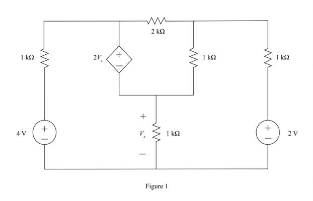
Chapter 5, Problem 74P
Use ThĂ©venin’s theorem to find the power supplied by the 2-V source in the circuit in Fig. P5.74.
Expert Solution & Answer
Want to see the full answer?
Check out a sample textbook solution
Students have asked these similar questions
Find Eigenvalues and Eigenvectors for the following matrices:
[5 -6 1
A = 1
1
0
3
0
1
Use Gauss-Jordan Elimination method to solve the following system:
4x1+5x2 + x3 = 2
x1-2x2-3x3 = 7
3x1 x2 2x3 = 1.
-
3. As the audio frequency of Fig. 11-7 goes down, what components of Fig.
12-4 must be modified for normal operation?
OD
C₂ 100
HF
R₁ 300
Re 300
ww
100A
R
8
Voc
Rz
10k
reset
output 3
R7
8
Voc
3
reset
output
Z
discharge
VR₁
5k
2
trigger
2 trigger
7
discharge
R 3
1k
5
control
voltage
threshold 6
5 control
voltage
6
threshold
GND
Rs
2k
C.
C.
100
GND
Uz LM555 1
Ce
0.01
U, LM555
0.01
8.01.4
PRO
Fig. 11-7
Audio lutput
Pulse width modulator
R4 1k
ww
C7
Re 1k
ww
R7 100
VR
50k
10μ
Ra
R10
C₁.
R1
3.9k
3.9k
0.14 100k
TO
w
Rs 51
82
3
H
10
Carrier
U₁
Ca
Input
A741
2.2
Us
MC1496
PWM signal
input
R2
0.1100k
Uz
A741
41
Cs
1
Re
10k
VR2
50k
VR3
100k
14
12
C3.
3% +
Ce
0.1
10μ
5
1A
HH
C
+12V
0.1
O PWM
Output
C
0.02-
R
100k +12 V
Demodulated
output
6
Ca
0.33
w
R
10k
R12
100k
ww 31
о
+
4A741
-12 V
Fig. 12-4 PWM demodulator
C
1500p
Chapter 5 Solutions
Basic Engineering Circuit Analysis
Ch. 5 - Find Io in the network in Fig. P5.1 using...Ch. 5 - Find Io in the network in Fig. P5.2 using...Ch. 5 - Find Io in the network in Fig. P5.3 using...Ch. 5 - Find Vo in the network in Fig. P5.4 using...Ch. 5 - Find Io in the circuit in Fig. P5.5 using...Ch. 5 - Find Io in the network in Fig. P5.6 using...Ch. 5 - Find Io in the circuit in Fig. P5.7 using...Ch. 5 - Find Vo in the network in Fig. P5.8 using...Ch. 5 - Find Vo in the network in Fig. P5.9 using...Ch. 5 - In the network in Fig. P5.l0, find using...
Ch. 5 - Find Io in the network in Fig. P5.11 using...Ch. 5 - Find Io in the network in Fig. P5.12 using...Ch. 5 - Find IA in the network in Fig. P5.13 using...Ch. 5 - Using superposition, find IA in the circuit in...Ch. 5 - Find IA in the network in Fig. P5.15 using...Ch. 5 - Using superposition, find Vo in the network in...Ch. 5 - Use superposition to find Io in the circuit in...Ch. 5 - Use superposition to find Io in the network in...Ch. 5 - Use superposition to find Vo in the circuit in...Ch. 5 - Find Vo in the circuit in Fig. P5.20 using...Ch. 5 - Find Io in the circuit in Fig. P5.21 using...Ch. 5 - Use superposition to find Io in the circuit in...Ch. 5 - Use superposition to find Io in the network in...Ch. 5 - Use superposition to find Io in the circuit in...Ch. 5 - Use Thévenins theorem to find Vo in the network...Ch. 5 - Use Thévenins theorem to find in the network in...Ch. 5 - Use Thévenins theorem to find Vo in the network...Ch. 5 - Find Io in the network in Fig. P5.28 using...Ch. 5 - Find Vo in the network in Fig. P5.28 using...Ch. 5 - Use Thévenins theorem to find 10 in the network...Ch. 5 - Find Vo in the network in Fig. P5.31 using...Ch. 5 - Find Io in the circuit in Fig. P5.32 using...Ch. 5 - Find Io in the network in Fig. P5.33 using...Ch. 5 - Find Io in the network in Fig. P5.34 using...Ch. 5 - Find Io in the circuit in Fig. P5.35 using...Ch. 5 - Find Io in the network in Fig. P5.36 using...Ch. 5 - Using Thévenins theorem, find IA in the circuit...Ch. 5 - Find Vo in the network in Fig. P5.38 using...Ch. 5 - Find Vo in the circuit in Fig. P5.39 using...Ch. 5 - Find Io in the circuit in Fig. P5.40 using...Ch. 5 - Find Vo in the network in Fig. P5.41 using...Ch. 5 - Find Io in the network in Fig. P5.42 using...Ch. 5 - Find Vo in Fig. P5.43 using Thévenins theorem.Ch. 5 - Use Thévenins theorem to find Vo in the circuit...Ch. 5 - Use Thévenins theorem to find Io in Fig. P5.45.Ch. 5 - Find Vo in the network in Fig. P5.46 using...Ch. 5 - Use Thévenins theorem to find Io in the network...Ch. 5 - Use Thévenins theorem to find Io in the circuit...Ch. 5 - Given the linear circuit in Fig. P5.49, it is...Ch. 5 - If an 8-k load is connected to the terminals of...Ch. 5 - Use Nortons theorem to find Io in the circuit in...Ch. 5 - Find Io in the network in Fig. P5.52 using Nortons...Ch. 5 - Use Nortons theorem to find Io in the circuit in...Ch. 5 - Use Nortons theorem to find Vo in the network in...Ch. 5 - Find Io in the network in Fig. P5.55 using Nortons...Ch. 5 - Use Nortons theorem to find Vo in the network in...Ch. 5 - Find Vo in the network in Fig. P5.57 using Nortons...Ch. 5 - Use Nortons theorem to find Io in the circuit in...Ch. 5 - Find Vo in the circuit in Fig. P5.59 using Nortons...Ch. 5 - Use Nortons theorem to find Io in the network in...Ch. 5 - Use Nortons theorem to find Io in the circuit in...Ch. 5 - In the network in Fig. P5.62, find Vo using...Ch. 5 - Use Thévenins theorem to find 10 in the circuit...Ch. 5 - Find Vo in the network in Fig. P5.64 using...Ch. 5 - Use Thévenins theorem to find Vo in the circuit...Ch. 5 - Find Io in the circuit in Fig. P5.66 using...Ch. 5 - Use Thévenins theorem to find Io in the circuit...Ch. 5 - Use Thévenins theorem to find Vo in the circuit...Ch. 5 - Find Vo in the network in Fig. P5.69 using...Ch. 5 - Use Nortons theorem to find Vo in the network in...Ch. 5 - Find Vo in the circuit in Fig. P5.71 using...Ch. 5 - Find Vo in the network in Fig. P5.72 using...Ch. 5 - Find Vo in the network in Fig. P5.73 using Nortons...Ch. 5 - Use Thévenins theorem to find the power supplied...Ch. 5 - Find Vo in the circuit in Fig. P5.75 using...Ch. 5 - Find Vo in the network in Fig. P5.76 using...Ch. 5 - Find Vo in the network in Fig. P5.77 using...Ch. 5 - Use Thévenins theorem to find I2 in the circuit...Ch. 5 - Use Thévenins theorem to find Vo in the circuit...Ch. 5 - Use Thévenins theorem to find Vo in the circuit...Ch. 5 - Use Thévenins theorem to find Io in the network...Ch. 5 - Use Thévenins theorem to find Vo in the network...Ch. 5 - Find the Thévenin equivalent of the network in...Ch. 5 - Find the Thévenin equivalent of the network in...Ch. 5 - Find the Thévenin equivalent of the circuit in...Ch. 5 - Find the Thévenin equivalent of the network in...Ch. 5 - Find the Thévenin equivalent circuit of the...Ch. 5 - Find Vo in the network in Fig. P5.88 using source...Ch. 5 - Find Io in the network in Fig. P5.89 using source...Ch. 5 - Use source transformation to find Vo in the...Ch. 5 - Find 10 in the network in Fig. P5.91 using source...Ch. 5 - Find Vo in the network in Fig. P5.92 using source...Ch. 5 - Use source transformation to find Io in the...Ch. 5 - Find the Thévenin equivalent circuit of the...Ch. 5 - Find Io in the circuit in Fig. P5.95 using source...Ch. 5 - Find Io in the network in Fig. P5.96 using source...Ch. 5 - Find Io in the network in Fig. P5.97 using source...Ch. 5 - Find Vo in the network in Fig. P5.98 using source...Ch. 5 - Find Io in the network in Fig. P5.99 using source...Ch. 5 - Find in the circuit in Fig. P5.100 using source...Ch. 5 - Use source transformation to find Io in the...Ch. 5 - Using source transformation, find Vo in the...Ch. 5 - Use source transformation to find Io in the...Ch. 5 - Use source transformation to find Io in the...Ch. 5 - Use source transformation to find 10 in the...Ch. 5 - Using source transformation, find 10 in the...Ch. 5 - Use source exchange to find Io in the network in...Ch. 5 - Use a combination of Y- transformation and source...Ch. 5 - Use source exchange to find Io in the circuit in...Ch. 5 - Use source exchange to find Io in the network in...Ch. 5 - Use source exchange to find Io in the network in...Ch. 5 - Find RL in the network in Fig. P5.112 in order to...Ch. 5 - In the network in Fig. P5.113, find RL for maximum...Ch. 5 - Find RL for maximum power transfer and the maximum...Ch. 5 - Find RL for maximum power transfer and the maximum...Ch. 5 - Find RL for maximum power transfer and the maximum...Ch. 5 - Find RL for maximum power transfer and the maximum...Ch. 5 - Determine the value of RL in the network in Fig....Ch. 5 - Find RL for maximum power transfer and the maximum...Ch. 5 - Find the value of RL in the network in Fig. P5.120...Ch. 5 - Find the value of RL for maximum power transfer...Ch. 5 - Find the maximum power that can be transferred to...Ch. 5 - In the network in Fig. P5.123, find the value of...Ch. 5 - In the network in Fig. P5.124, find the value of...Ch. 5 - Find the value of RL in Fig. P5.125 for maximum...Ch. 5 - Calculate the maximum power that can be...Ch. 5 - Find RL for maximum power transfer and the maximum...Ch. 5 - Find the value of RL in Fig. P5.128 for maximum...Ch. 5 - A cell phone antenna picks up a call. If the...Ch. 5 - Some young engineers at the local electrical...Ch. 5 - Determine the maximum power that can be delivered...Ch. 5 - Find the value of the load RL in the network in...Ch. 5 - Find the value of RL in the network in fig. 5PFE-3...Ch. 5 - What is the current I in Fig. 5PFE4? a. 8 Ac. 0 A...Ch. 5 - What is the open-circuit voltage Voc at terminals...
Additional Engineering Textbook Solutions
Find more solutions based on key concepts
An object of classproduces truly random numbers.
Java How to Program, Early Objects (11th Edition) (Deitel: How to Program)
Fill in the blanks in each of the following statements: A relation that has no partial functional dependencies ...
Modern Database Management
Why is it good advice to indent all the statements inside a set of braces?
Starting Out with Java: From Control Structures through Objects (7th Edition) (What's New in Computer Science)
Why do some standard SQL-92 statements fail to run successfully in Microsoft Access?
Database Concepts (8th Edition)
Write code that will fill the following array a with numbers typed at the keyboard: int [][] a = new int [4][5]...
Java: An Introduction to Problem Solving and Programming (8th Edition)
// This program displays the sum of the numbers 1-100. #include iostream using namespace std; int main() { 1nt ...
Starting Out with C++ from Control Structures to Objects (9th Edition)
Knowledge Booster


Learn more about
Need a deep-dive on the concept behind this application? Look no further. Learn more about this topic, electrical-engineering and related others by exploring similar questions and additional content below.Similar questions
- DUC 1. In Fig. 12-4, what are the functions of the VR1 and VR2? 2. In Fig. 12-4, what is the function of the VR3? VR₁ 50k C₁ R1 0.1 100k Carrier Input U₁ A741 PWM signal input R41k www Re 1k w C7 ± 10μT R7 100 ww =L H C4 2.2 H W82 Rs 51 3 10 U3 MC1496 C2 R2 U2 A741 22 0.1 100k VR2 50k VR3 100kr 14 C3 10μ 1k 0.1 4 5 6 12 m Re 10k R9 R102 3.9k 3.9k HHI C10 0.1 -0 +12V C11 R 0.02 100k +12 V Demodulated output C R11 R12 A741 0.33 10k 100k -12 V Ca 1μ C12 1500p PRODUC Fig. 12-4 PWM demodulator PRODUCTSarrow_forward10.37 Use mesh analysis to find currents I₁, I2, and I3 in the circuit of Fig. 10.82. ML 120-90° V 120 -30° V Figure 10.82 For Prob. 10.37. N N Z=80-135arrow_forward3. Find the phasor current I。 in the circuit shown below. Be aware of the direction markings. (15 pts) 1052 I 5057 ①520 Amps 2012 j5052arrow_forward
- 10.93 Figure 10.135 shows a Colpitts oscillator. Show that the ed oscillation frequency is 1 fo= 2π √√LCT where CTC₁C2/(C₁ + C₂). Assume R; >>> R₁ + Rf ww Vo L m C₂ C₁ 5 Xci Figure 10.135 A Colpitts oscillator; for Prob. 10.93. (Hint: Set the imaginary part of the impedance in the feedback circuit equal to zero.)arrow_forwardDetermine (a) the average and (b) rms values of the periodiccurrent waveform shown in Fig. P8.3.arrow_forward10.68 Find the Thevenin equivalent at terminals a-b in the circuit of Fig. 10.111. ML 6 sin 10t V 492 Figure 10.111 For Prob. 10.68. 5913 + 410 + -2 F 20 1H Vo obarrow_forward
- 10.79 For the op amp circuit in Fig. 10.122, obtain Vo. 5 cos 10³t V(+ Figure 10.122 For Prob. 10.79. 10 ΚΩ www 20 ΚΩ www 0.1 µF 40 ΚΩ 0.2 μFarrow_forward10.19 Obtain V, in Fig. 10.68 using nodal analysis. # ML ΖΩ j20 m 12/0° V 492 (+ ww www ' < ་ + V -j4 0.2V Figure 10.68 For Prob. 10.19.arrow_forward10.47 Determine i, in the circuit of Fig. 10.92, using the superposition principle. ML 10 sin(t -30°) V 1Ω www Figure 10.92 For Prob. 10.47. 96 F 202 www 24 V +) 2 H m io 2 cos 3t www 42arrow_forward
- 10.53 Use the concept of source transformation to find V, in the circuit of Fig. 10.97. 492 www -j30 j40 m + 20/0° V(+ j20 ΖΩ www -120 V ° Figure 10.97 For Prob. 10.53.arrow_forward2. Given you have a real valued signal with the following single sided baseband signal spectrum: ↑ ❘m(f)| A f=0 500 750 Sketch the frequency domain of |X(f)| given: a. x1(t) =m(t)cos(2**5000*) b. x2(t)=m(t)cos(2**600) Frequency (Hz)arrow_forwardwhat is deference between full Adder and Half?arrow_forward
arrow_back_ios
SEE MORE QUESTIONS
arrow_forward_ios
Recommended textbooks for you
 Introductory Circuit Analysis (13th Edition)Electrical EngineeringISBN:9780133923605Author:Robert L. BoylestadPublisher:PEARSON
 Delmar's Standard Textbook Of ElectricityElectrical EngineeringISBN:9781337900348Author:Stephen L. HermanPublisher:Cengage Learning
 Programmable Logic ControllersElectrical EngineeringISBN:9780073373843Author:Frank D. PetruzellaPublisher:McGraw-Hill Education
 Fundamentals of Electric CircuitsElectrical EngineeringISBN:9780078028229Author:Charles K Alexander, Matthew SadikuPublisher:McGraw-Hill Education
 Electric Circuits. (11th Edition)Electrical EngineeringISBN:9780134746968Author:James W. Nilsson, Susan RiedelPublisher:PEARSON
 Engineering ElectromagneticsElectrical EngineeringISBN:9780078028151Author:Hayt, William H. (william Hart), Jr, BUCK, John A.Publisher:Mcgraw-hill Education,
Introductory Circuit Analysis (13th Edition)
Electrical Engineering
ISBN:9780133923605
Author:Robert L. Boylestad
Publisher:PEARSON
Delmar's Standard Textbook Of Electricity
Electrical Engineering
ISBN:9781337900348
Author:Stephen L. Herman
Publisher:Cengage Learning
Programmable Logic Controllers
Electrical Engineering
ISBN:9780073373843
Author:Frank D. Petruzella
Publisher:McGraw-Hill Education
Fundamentals of Electric Circuits
Electrical Engineering
ISBN:9780078028229
Author:Charles K Alexander, Matthew Sadiku
Publisher:McGraw-Hill Education
Electric Circuits. (11th Edition)
Electrical Engineering
ISBN:9780134746968
Author:James W. Nilsson, Susan Riedel
Publisher:PEARSON
Engineering Electromagnetics
Electrical Engineering
ISBN:9780078028151
Author:Hayt, William H. (william Hart), Jr, BUCK, John A.
Publisher:Mcgraw-hill Education,
Maximum Power Transfer Theorem Using Nodal Analysis & Thevenin Equivalent Circuits; Author: The Organic Chemistry Tutor;https://www.youtube.com/watch?v=8CA6ZNXgI-Y;License: Standard Youtube License