
Basic Engineering Circuit Analysis
11th Edition
ISBN: 9781118539293
Author: J. David Irwin, R. Mark Nelms
Publisher: WILEY
expand_more
expand_more
format_list_bulleted
Concept explainers
Videos
Textbook Question
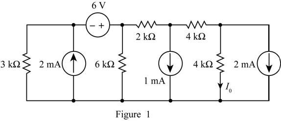
Chapter 5, Problem 96P
Find
Expert Solution & Answer
Want to see the full answer?
Check out a sample textbook solution
Students have asked these similar questions
7.48 Determine the Thevenin equivalent of the circuit inFig. P7.48 at terminals (a,b), given thatVs(t) = 12cos 2500t V,Is(t) = 0.5cos(2500t −30◦) A.
1. In the following closed-loop system, a PD controller of the form K(s + 5) is used. Design the gain K such
that the system achieves an overshoot of 16%. Calculate the settling time and peak time for the PD
controlled system.
Compensator
R(s) +
E(s)
Plant
1
C(s)
K(s+Zc)
(s+1)(s+2)(s+5)
Find Vo
Chapter 5 Solutions
Basic Engineering Circuit Analysis
Ch. 5 - Find Io in the network in Fig. P5.1 using...Ch. 5 - Find Io in the network in Fig. P5.2 using...Ch. 5 - Find Io in the network in Fig. P5.3 using...Ch. 5 - Find Vo in the network in Fig. P5.4 using...Ch. 5 - Find Io in the circuit in Fig. P5.5 using...Ch. 5 - Find Io in the network in Fig. P5.6 using...Ch. 5 - Find Io in the circuit in Fig. P5.7 using...Ch. 5 - Find Vo in the network in Fig. P5.8 using...Ch. 5 - Find Vo in the network in Fig. P5.9 using...Ch. 5 - In the network in Fig. P5.l0, find using...
Ch. 5 - Find Io in the network in Fig. P5.11 using...Ch. 5 - Find Io in the network in Fig. P5.12 using...Ch. 5 - Find IA in the network in Fig. P5.13 using...Ch. 5 - Using superposition, find IA in the circuit in...Ch. 5 - Find IA in the network in Fig. P5.15 using...Ch. 5 - Using superposition, find Vo in the network in...Ch. 5 - Use superposition to find Io in the circuit in...Ch. 5 - Use superposition to find Io in the network in...Ch. 5 - Use superposition to find Vo in the circuit in...Ch. 5 - Find Vo in the circuit in Fig. P5.20 using...Ch. 5 - Find Io in the circuit in Fig. P5.21 using...Ch. 5 - Use superposition to find Io in the circuit in...Ch. 5 - Use superposition to find Io in the network in...Ch. 5 - Use superposition to find Io in the circuit in...Ch. 5 - Use Thévenins theorem to find Vo in the network...Ch. 5 - Use Thévenins theorem to find in the network in...Ch. 5 - Use Thévenins theorem to find Vo in the network...Ch. 5 - Find Io in the network in Fig. P5.28 using...Ch. 5 - Find Vo in the network in Fig. P5.28 using...Ch. 5 - Use Thévenins theorem to find 10 in the network...Ch. 5 - Find Vo in the network in Fig. P5.31 using...Ch. 5 - Find Io in the circuit in Fig. P5.32 using...Ch. 5 - Find Io in the network in Fig. P5.33 using...Ch. 5 - Find Io in the network in Fig. P5.34 using...Ch. 5 - Find Io in the circuit in Fig. P5.35 using...Ch. 5 - Find Io in the network in Fig. P5.36 using...Ch. 5 - Using Thévenins theorem, find IA in the circuit...Ch. 5 - Find Vo in the network in Fig. P5.38 using...Ch. 5 - Find Vo in the circuit in Fig. P5.39 using...Ch. 5 - Find Io in the circuit in Fig. P5.40 using...Ch. 5 - Find Vo in the network in Fig. P5.41 using...Ch. 5 - Find Io in the network in Fig. P5.42 using...Ch. 5 - Find Vo in Fig. P5.43 using Thévenins theorem.Ch. 5 - Use Thévenins theorem to find Vo in the circuit...Ch. 5 - Use Thévenins theorem to find Io in Fig. P5.45.Ch. 5 - Find Vo in the network in Fig. P5.46 using...Ch. 5 - Use Thévenins theorem to find Io in the network...Ch. 5 - Use Thévenins theorem to find Io in the circuit...Ch. 5 - Given the linear circuit in Fig. P5.49, it is...Ch. 5 - If an 8-k load is connected to the terminals of...Ch. 5 - Use Nortons theorem to find Io in the circuit in...Ch. 5 - Find Io in the network in Fig. P5.52 using Nortons...Ch. 5 - Use Nortons theorem to find Io in the circuit in...Ch. 5 - Use Nortons theorem to find Vo in the network in...Ch. 5 - Find Io in the network in Fig. P5.55 using Nortons...Ch. 5 - Use Nortons theorem to find Vo in the network in...Ch. 5 - Find Vo in the network in Fig. P5.57 using Nortons...Ch. 5 - Use Nortons theorem to find Io in the circuit in...Ch. 5 - Find Vo in the circuit in Fig. P5.59 using Nortons...Ch. 5 - Use Nortons theorem to find Io in the network in...Ch. 5 - Use Nortons theorem to find Io in the circuit in...Ch. 5 - In the network in Fig. P5.62, find Vo using...Ch. 5 - Use Thévenins theorem to find 10 in the circuit...Ch. 5 - Find Vo in the network in Fig. P5.64 using...Ch. 5 - Use Thévenins theorem to find Vo in the circuit...Ch. 5 - Find Io in the circuit in Fig. P5.66 using...Ch. 5 - Use Thévenins theorem to find Io in the circuit...Ch. 5 - Use Thévenins theorem to find Vo in the circuit...Ch. 5 - Find Vo in the network in Fig. P5.69 using...Ch. 5 - Use Nortons theorem to find Vo in the network in...Ch. 5 - Find Vo in the circuit in Fig. P5.71 using...Ch. 5 - Find Vo in the network in Fig. P5.72 using...Ch. 5 - Find Vo in the network in Fig. P5.73 using Nortons...Ch. 5 - Use Thévenins theorem to find the power supplied...Ch. 5 - Find Vo in the circuit in Fig. P5.75 using...Ch. 5 - Find Vo in the network in Fig. P5.76 using...Ch. 5 - Find Vo in the network in Fig. P5.77 using...Ch. 5 - Use Thévenins theorem to find I2 in the circuit...Ch. 5 - Use Thévenins theorem to find Vo in the circuit...Ch. 5 - Use Thévenins theorem to find Vo in the circuit...Ch. 5 - Use Thévenins theorem to find Io in the network...Ch. 5 - Use Thévenins theorem to find Vo in the network...Ch. 5 - Find the Thévenin equivalent of the network in...Ch. 5 - Find the Thévenin equivalent of the network in...Ch. 5 - Find the Thévenin equivalent of the circuit in...Ch. 5 - Find the Thévenin equivalent of the network in...Ch. 5 - Find the Thévenin equivalent circuit of the...Ch. 5 - Find Vo in the network in Fig. P5.88 using source...Ch. 5 - Find Io in the network in Fig. P5.89 using source...Ch. 5 - Use source transformation to find Vo in the...Ch. 5 - Find 10 in the network in Fig. P5.91 using source...Ch. 5 - Find Vo in the network in Fig. P5.92 using source...Ch. 5 - Use source transformation to find Io in the...Ch. 5 - Find the Thévenin equivalent circuit of the...Ch. 5 - Find Io in the circuit in Fig. P5.95 using source...Ch. 5 - Find Io in the network in Fig. P5.96 using source...Ch. 5 - Find Io in the network in Fig. P5.97 using source...Ch. 5 - Find Vo in the network in Fig. P5.98 using source...Ch. 5 - Find Io in the network in Fig. P5.99 using source...Ch. 5 - Find in the circuit in Fig. P5.100 using source...Ch. 5 - Use source transformation to find Io in the...Ch. 5 - Using source transformation, find Vo in the...Ch. 5 - Use source transformation to find Io in the...Ch. 5 - Use source transformation to find Io in the...Ch. 5 - Use source transformation to find 10 in the...Ch. 5 - Using source transformation, find 10 in the...Ch. 5 - Use source exchange to find Io in the network in...Ch. 5 - Use a combination of Y- transformation and source...Ch. 5 - Use source exchange to find Io in the circuit in...Ch. 5 - Use source exchange to find Io in the network in...Ch. 5 - Use source exchange to find Io in the network in...Ch. 5 - Find RL in the network in Fig. P5.112 in order to...Ch. 5 - In the network in Fig. P5.113, find RL for maximum...Ch. 5 - Find RL for maximum power transfer and the maximum...Ch. 5 - Find RL for maximum power transfer and the maximum...Ch. 5 - Find RL for maximum power transfer and the maximum...Ch. 5 - Find RL for maximum power transfer and the maximum...Ch. 5 - Determine the value of RL in the network in Fig....Ch. 5 - Find RL for maximum power transfer and the maximum...Ch. 5 - Find the value of RL in the network in Fig. P5.120...Ch. 5 - Find the value of RL for maximum power transfer...Ch. 5 - Find the maximum power that can be transferred to...Ch. 5 - In the network in Fig. P5.123, find the value of...Ch. 5 - In the network in Fig. P5.124, find the value of...Ch. 5 - Find the value of RL in Fig. P5.125 for maximum...Ch. 5 - Calculate the maximum power that can be...Ch. 5 - Find RL for maximum power transfer and the maximum...Ch. 5 - Find the value of RL in Fig. P5.128 for maximum...Ch. 5 - A cell phone antenna picks up a call. If the...Ch. 5 - Some young engineers at the local electrical...Ch. 5 - Determine the maximum power that can be delivered...Ch. 5 - Find the value of the load RL in the network in...Ch. 5 - Find the value of RL in the network in fig. 5PFE-3...Ch. 5 - What is the current I in Fig. 5PFE4? a. 8 Ac. 0 A...Ch. 5 - What is the open-circuit voltage Voc at terminals...
Additional Engineering Textbook Solutions
Find more solutions based on key concepts
Give an example of a data constraint.
Database Concepts (8th Edition)
What is the difference between the roughing teeth and the finishing teeth in a typical pull broach?
Degarmo's Materials And Processes In Manufacturing
Essay Class Design an Essay class that extends the GradedActivity class presented in this chapter. The Essay cl...
Starting Out with Programming Logic and Design (5th Edition) (What's New in Computer Science)
(Temperature Conversions) Implement the following integer methods: Method celsius returns the Celsius equivalen...
Java How to Program, Early Objects (11th Edition) (Deitel: How to Program)
How does the typing system of PHP and JavaScript differ from that of Java?
Concepts Of Programming Languages
3.1 Discuss the differences between an error and a residual.
Elementary Surveying: An Introduction To Geomatics (15th Edition)
Knowledge Booster


Learn more about
Need a deep-dive on the concept behind this application? Look no further. Learn more about this topic, electrical-engineering and related others by exploring similar questions and additional content below.Similar questions
- 3. Use MATLAB to generate the Nyquist plot for the following system. Then, apply the Nyquist stability criterion to determine the range of K values that ensure the stability of the closed-loop system. R(s)+ K C(s) (s+2) 1 (s + 4)(s+6)arrow_forward4. Please find the stability margins from the following Bode diagrams. Bode Diagram Phase (deg) Magnitude (dB) 50 -100 -90 -135 -180 -270 10" 10° Frequency (rad/sec) 10'arrow_forward2. Please use asymptotes to draw the Bode diagrams of the following transfer function. Please label the axes to show the cut-off frequencies and key values on vertical axes and label each asymptote with its slope. G(s) s+10 s(s²+10s+100)arrow_forward
- Find the Z-transform including the region of convergence for the following function 12 (¹)" [u(n) – u(n − 5)] -arrow_forwardFind the inverse Z-traform of X(z)= z 2 +z (z-0.125)³ (z-0.25)arrow_forwardA separately excited 6-kilowatt generator has a terminal voltage of 135V at no load. At full load, the terminal voltage is 120V with speed and field excitation unchanged. Armature resistance = = 0.25 ohm. A. What is the amount of voltage decrease caused by armature reaction and the voltage regulation?arrow_forward
arrow_back_ios
SEE MORE QUESTIONS
arrow_forward_ios
Recommended textbooks for you
 Introductory Circuit Analysis (13th Edition)Electrical EngineeringISBN:9780133923605Author:Robert L. BoylestadPublisher:PEARSON
 Delmar's Standard Textbook Of ElectricityElectrical EngineeringISBN:9781337900348Author:Stephen L. HermanPublisher:Cengage Learning
 Programmable Logic ControllersElectrical EngineeringISBN:9780073373843Author:Frank D. PetruzellaPublisher:McGraw-Hill Education
 Fundamentals of Electric CircuitsElectrical EngineeringISBN:9780078028229Author:Charles K Alexander, Matthew SadikuPublisher:McGraw-Hill Education
 Electric Circuits. (11th Edition)Electrical EngineeringISBN:9780134746968Author:James W. Nilsson, Susan RiedelPublisher:PEARSON
 Engineering ElectromagneticsElectrical EngineeringISBN:9780078028151Author:Hayt, William H. (william Hart), Jr, BUCK, John A.Publisher:Mcgraw-hill Education,
Introductory Circuit Analysis (13th Edition)
Electrical Engineering
ISBN:9780133923605
Author:Robert L. Boylestad
Publisher:PEARSON
Delmar's Standard Textbook Of Electricity
Electrical Engineering
ISBN:9781337900348
Author:Stephen L. Herman
Publisher:Cengage Learning
Programmable Logic Controllers
Electrical Engineering
ISBN:9780073373843
Author:Frank D. Petruzella
Publisher:McGraw-Hill Education
Fundamentals of Electric Circuits
Electrical Engineering
ISBN:9780078028229
Author:Charles K Alexander, Matthew Sadiku
Publisher:McGraw-Hill Education
Electric Circuits. (11th Edition)
Electrical Engineering
ISBN:9780134746968
Author:James W. Nilsson, Susan Riedel
Publisher:PEARSON
Engineering Electromagnetics
Electrical Engineering
ISBN:9780078028151
Author:Hayt, William H. (william Hart), Jr, BUCK, John A.
Publisher:Mcgraw-hill Education,
Maximum Power Transfer Theorem Using Nodal Analysis & Thevenin Equivalent Circuits; Author: The Organic Chemistry Tutor;https://www.youtube.com/watch?v=8CA6ZNXgI-Y;License: Standard Youtube License