
Basic Engineering Circuit Analysis
11th Edition
ISBN: 9781118539293
Author: J. David Irwin, R. Mark Nelms
Publisher: WILEY
expand_more
expand_more
format_list_bulleted
Concept explainers
Videos
Textbook Question
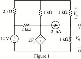
Chapter 5, Problem 76P
Find
Expert Solution & Answer

Trending nowThis is a popular solution!

Students have asked these similar questions
An electric resistance space heater is designed such that it resembles a rectangular box 55 cm high, 75 cm long, and 20
cm wide filled with 45 kg of oil. The heater is to be placed against a wall, and thus heat transfer from its back surface is
negligible. The surface temperature of the heater is not to exceed 75°C in a room at 25°C for safety considerations.
The emissivity of the outer surface of the heater is 0.8 and the average temperature of the ceiling and wall surfaces is the
same as the room air temperature.
The properties of air at 1 atm and the film temperature are: k = 0.02753 W/m-°C, v=1.798 x 10⁻⁵ m²/s, Pr = 0.7228, and ẞ=
0.003096K-1
Wall
T₁ =75°C
Oil
€ = 0.8
Electric heater
Heating element
Disregarding heat transfer from the bottom and top surfaces of the heater in anticipation that the top surface will be used as a shelf,
determine the power rating of the heater in W.
The power rating of the heater is
W.
circuit 2
Suppose you have 8 LED's connected to port-B (Bo-B7) of PIC16F877A and one switch
connected to port-D (Do) as shown in figure below. Write a program code that performs a
nibble (4-bits) toggling: if the switch is released then LED's (Bo to B3) are OFF and LED's
(B4 to B7) are ON, while if the switch is pressed then LED's (Bo to B3) are ON and LED's
(B4 to B7) are OFF. Use 300ms delay for each case with 4MHz frequency.
13
14
22 NATHON 20
U1
OSC1/CLKIN
U2
33
REOINT
20
34
OSC2/CLKOUT
19
RB1
35
3
18
RB2
RADIANO debt0RB3PGM
30
4
17
37
5
10
RA1/AN1
RB4
38
RA2/ANZ/VREF-/CVREF
15
RB5
39097
RA3/AN3VREF RB6/PGC
7
14
40
RA4/TOCK/C1OUT
13
RB7/PGO
RAS/ANA/SS/CZOUT
15
RCO/T1OSO/TICKI
10
11
REQIANS/RD
18
RC1/T10S/CCP2
17
10
RE1/AN/WR
REZ/ANTICS
MCLR/Vpp/THV
RC2/CCP1
LED-BARGRAPH-RED
RC3/SCK/SCL
RC4/SDUSDA
RC5/SDO
Eng of ROSTX/CX
RC7/RX/DT
RDO/PSPO
RD1/PSP1
RD2PSP2
RO3/PSP3
RD4/PSP4
ROS/PSP5
RD6/PSP6
RD7/PSP7
PIC16F877A
+5V
R1
100R
Chapter 5 Solutions
Basic Engineering Circuit Analysis
Ch. 5 - Find Io in the network in Fig. P5.1 using...Ch. 5 - Find Io in the network in Fig. P5.2 using...Ch. 5 - Find Io in the network in Fig. P5.3 using...Ch. 5 - Find Vo in the network in Fig. P5.4 using...Ch. 5 - Find Io in the circuit in Fig. P5.5 using...Ch. 5 - Find Io in the network in Fig. P5.6 using...Ch. 5 - Find Io in the circuit in Fig. P5.7 using...Ch. 5 - Find Vo in the network in Fig. P5.8 using...Ch. 5 - Find Vo in the network in Fig. P5.9 using...Ch. 5 - In the network in Fig. P5.l0, find using...
Ch. 5 - Find Io in the network in Fig. P5.11 using...Ch. 5 - Find Io in the network in Fig. P5.12 using...Ch. 5 - Find IA in the network in Fig. P5.13 using...Ch. 5 - Using superposition, find IA in the circuit in...Ch. 5 - Find IA in the network in Fig. P5.15 using...Ch. 5 - Using superposition, find Vo in the network in...Ch. 5 - Use superposition to find Io in the circuit in...Ch. 5 - Use superposition to find Io in the network in...Ch. 5 - Use superposition to find Vo in the circuit in...Ch. 5 - Find Vo in the circuit in Fig. P5.20 using...Ch. 5 - Find Io in the circuit in Fig. P5.21 using...Ch. 5 - Use superposition to find Io in the circuit in...Ch. 5 - Use superposition to find Io in the network in...Ch. 5 - Use superposition to find Io in the circuit in...Ch. 5 - Use Thévenins theorem to find Vo in the network...Ch. 5 - Use Thévenins theorem to find in the network in...Ch. 5 - Use Thévenins theorem to find Vo in the network...Ch. 5 - Find Io in the network in Fig. P5.28 using...Ch. 5 - Find Vo in the network in Fig. P5.28 using...Ch. 5 - Use Thévenins theorem to find 10 in the network...Ch. 5 - Find Vo in the network in Fig. P5.31 using...Ch. 5 - Find Io in the circuit in Fig. P5.32 using...Ch. 5 - Find Io in the network in Fig. P5.33 using...Ch. 5 - Find Io in the network in Fig. P5.34 using...Ch. 5 - Find Io in the circuit in Fig. P5.35 using...Ch. 5 - Find Io in the network in Fig. P5.36 using...Ch. 5 - Using Thévenins theorem, find IA in the circuit...Ch. 5 - Find Vo in the network in Fig. P5.38 using...Ch. 5 - Find Vo in the circuit in Fig. P5.39 using...Ch. 5 - Find Io in the circuit in Fig. P5.40 using...Ch. 5 - Find Vo in the network in Fig. P5.41 using...Ch. 5 - Find Io in the network in Fig. P5.42 using...Ch. 5 - Find Vo in Fig. P5.43 using Thévenins theorem.Ch. 5 - Use Thévenins theorem to find Vo in the circuit...Ch. 5 - Use Thévenins theorem to find Io in Fig. P5.45.Ch. 5 - Find Vo in the network in Fig. P5.46 using...Ch. 5 - Use Thévenins theorem to find Io in the network...Ch. 5 - Use Thévenins theorem to find Io in the circuit...Ch. 5 - Given the linear circuit in Fig. P5.49, it is...Ch. 5 - If an 8-k load is connected to the terminals of...Ch. 5 - Use Nortons theorem to find Io in the circuit in...Ch. 5 - Find Io in the network in Fig. P5.52 using Nortons...Ch. 5 - Use Nortons theorem to find Io in the circuit in...Ch. 5 - Use Nortons theorem to find Vo in the network in...Ch. 5 - Find Io in the network in Fig. P5.55 using Nortons...Ch. 5 - Use Nortons theorem to find Vo in the network in...Ch. 5 - Find Vo in the network in Fig. P5.57 using Nortons...Ch. 5 - Use Nortons theorem to find Io in the circuit in...Ch. 5 - Find Vo in the circuit in Fig. P5.59 using Nortons...Ch. 5 - Use Nortons theorem to find Io in the network in...Ch. 5 - Use Nortons theorem to find Io in the circuit in...Ch. 5 - In the network in Fig. P5.62, find Vo using...Ch. 5 - Use Thévenins theorem to find 10 in the circuit...Ch. 5 - Find Vo in the network in Fig. P5.64 using...Ch. 5 - Use Thévenins theorem to find Vo in the circuit...Ch. 5 - Find Io in the circuit in Fig. P5.66 using...Ch. 5 - Use Thévenins theorem to find Io in the circuit...Ch. 5 - Use Thévenins theorem to find Vo in the circuit...Ch. 5 - Find Vo in the network in Fig. P5.69 using...Ch. 5 - Use Nortons theorem to find Vo in the network in...Ch. 5 - Find Vo in the circuit in Fig. P5.71 using...Ch. 5 - Find Vo in the network in Fig. P5.72 using...Ch. 5 - Find Vo in the network in Fig. P5.73 using Nortons...Ch. 5 - Use Thévenins theorem to find the power supplied...Ch. 5 - Find Vo in the circuit in Fig. P5.75 using...Ch. 5 - Find Vo in the network in Fig. P5.76 using...Ch. 5 - Find Vo in the network in Fig. P5.77 using...Ch. 5 - Use Thévenins theorem to find I2 in the circuit...Ch. 5 - Use Thévenins theorem to find Vo in the circuit...Ch. 5 - Use Thévenins theorem to find Vo in the circuit...Ch. 5 - Use Thévenins theorem to find Io in the network...Ch. 5 - Use Thévenins theorem to find Vo in the network...Ch. 5 - Find the Thévenin equivalent of the network in...Ch. 5 - Find the Thévenin equivalent of the network in...Ch. 5 - Find the Thévenin equivalent of the circuit in...Ch. 5 - Find the Thévenin equivalent of the network in...Ch. 5 - Find the Thévenin equivalent circuit of the...Ch. 5 - Find Vo in the network in Fig. P5.88 using source...Ch. 5 - Find Io in the network in Fig. P5.89 using source...Ch. 5 - Use source transformation to find Vo in the...Ch. 5 - Find 10 in the network in Fig. P5.91 using source...Ch. 5 - Find Vo in the network in Fig. P5.92 using source...Ch. 5 - Use source transformation to find Io in the...Ch. 5 - Find the Thévenin equivalent circuit of the...Ch. 5 - Find Io in the circuit in Fig. P5.95 using source...Ch. 5 - Find Io in the network in Fig. P5.96 using source...Ch. 5 - Find Io in the network in Fig. P5.97 using source...Ch. 5 - Find Vo in the network in Fig. P5.98 using source...Ch. 5 - Find Io in the network in Fig. P5.99 using source...Ch. 5 - Find in the circuit in Fig. P5.100 using source...Ch. 5 - Use source transformation to find Io in the...Ch. 5 - Using source transformation, find Vo in the...Ch. 5 - Use source transformation to find Io in the...Ch. 5 - Use source transformation to find Io in the...Ch. 5 - Use source transformation to find 10 in the...Ch. 5 - Using source transformation, find 10 in the...Ch. 5 - Use source exchange to find Io in the network in...Ch. 5 - Use a combination of Y- transformation and source...Ch. 5 - Use source exchange to find Io in the circuit in...Ch. 5 - Use source exchange to find Io in the network in...Ch. 5 - Use source exchange to find Io in the network in...Ch. 5 - Find RL in the network in Fig. P5.112 in order to...Ch. 5 - In the network in Fig. P5.113, find RL for maximum...Ch. 5 - Find RL for maximum power transfer and the maximum...Ch. 5 - Find RL for maximum power transfer and the maximum...Ch. 5 - Find RL for maximum power transfer and the maximum...Ch. 5 - Find RL for maximum power transfer and the maximum...Ch. 5 - Determine the value of RL in the network in Fig....Ch. 5 - Find RL for maximum power transfer and the maximum...Ch. 5 - Find the value of RL in the network in Fig. P5.120...Ch. 5 - Find the value of RL for maximum power transfer...Ch. 5 - Find the maximum power that can be transferred to...Ch. 5 - In the network in Fig. P5.123, find the value of...Ch. 5 - In the network in Fig. P5.124, find the value of...Ch. 5 - Find the value of RL in Fig. P5.125 for maximum...Ch. 5 - Calculate the maximum power that can be...Ch. 5 - Find RL for maximum power transfer and the maximum...Ch. 5 - Find the value of RL in Fig. P5.128 for maximum...Ch. 5 - A cell phone antenna picks up a call. If the...Ch. 5 - Some young engineers at the local electrical...Ch. 5 - Determine the maximum power that can be delivered...Ch. 5 - Find the value of the load RL in the network in...Ch. 5 - Find the value of RL in the network in fig. 5PFE-3...Ch. 5 - What is the current I in Fig. 5PFE4? a. 8 Ac. 0 A...Ch. 5 - What is the open-circuit voltage Voc at terminals...
Additional Engineering Textbook Solutions
Find more solutions based on key concepts
3.1 Discuss the differences between an error and a residual.
Elementary Surveying: An Introduction To Geomatics (15th Edition)
Find the error in the following class: public class FindTheError { public int square(int number) { return numbe...
Starting Out with Java: From Control Structures through Objects (7th Edition) (What's New in Computer Science)
Describe the advantages and disadvantages of three-tier architectures.
Modern Database Management
Write a program that allows the user to enter a number of quarters, dimes, and nickels and then outputs the mon...
Problem Solving with C++ (10th Edition)
For the circuit shown, find (a) the voltage υ, (b) the power delivered to the circuit by the current source, an...
Electric Circuits. (11th Edition)
Add methods to the Person class from Self-Test Question 16 to perform the following tasks: Set the name attribu...
Java: An Introduction to Problem Solving and Programming (8th Edition)
Knowledge Booster


Learn more about
Need a deep-dive on the concept behind this application? Look no further. Learn more about this topic, electrical-engineering and related others by exploring similar questions and additional content below.Similar questions
- Write a PIC16F877A program that flash ON the 8-LED's connected to port-B by using two switches connected to port-D (Do & D₁) as shown in figure below, according to the following scenarios: (Hint: Use 500ms delay for each case with 4MHz frequency) 1. When Do=1 then B₁,B3,B, are ON. 2. When Do 0 then Bo,B2,B4, B5, B6 are ON. 3. When D₁=1 then B4,B,,B6,B7 are ON. 4. When D₁-0 then Bo,B1,B2,B3 are ON. U1 5 33 OSC/CLION OSC2/CLKOUT ROOINT RB1 35 RB2 20 17 RACIANO RESPOM RATANT RAZIANZ/VREF-CVREF RBS RA3/AN3/VREF+ REPOC 39 14 40 RA4/TOCK C1OUT 13 RB7/PGO 12 RASIAN/SCOUT 15 ROOT1050/TICK +5V REGIANERD REVANDVIR REZANTICS RCMT10SUCCP2 17 RC2/CCP1 LED-BARGRAPH-RED RC3SCHISCL 23 --- MCUANTV RC4/SOSDA 24 RCS/SDO RCB/TICK RC7/RXDT 25 ROOPSPO RDMPSP1 RD2PSF2 RO3PSP3 RD4PSP4 RDSPSPS PIC16F877A ROOPSP RO7/PSP7 R2 R1 100R 100Rarrow_forwardQuestion 5 The following data were obtained from testing a 48-kVA 240/4800 V step up transformer. Open-circuit test Short-circuit test Voltage (V) 240 150 Current (I) 2 10 Power (W) 120 600 Determine the equivalent circuit of the transformer as viewed from the primary side. Ans: Rc = 480 ohm, Xm = 123.94 ohm, Reqp = 0.015 ohm, Xeqp = 0.034 ohmarrow_forwardFrom the following mass-spring system, obtain its transfer function and pole-zero wwwwwwww wwww diagram in MATLAB. Analyze how stability varies when entering values. wwwww (4)x1 ▷ x(t) M f(t) B f(t) is the input variable and x(t) is the controlled variable.arrow_forward
- R2 L3 C5 BRF_OUT HH Sine_OUT 100 1m 100n C3 C4 100n 100n Figure 9. Square to sine waveform converter circuit How do we make sense of this? First, we note that R2 and C3 form a first order low pass filter and L3 and C4 form another low pass filter. Both low pass filters have been set at the same cutoff frequency. The combination of both form a two stage filter to remove the high frequency content present in the DAB signal. Capacitor C5 is used to remove any residual DC offset in the signal. But let's just deal with the AC steady state response, which means that you don't need to know any of these details, and then can conveniently treat this circuit as a blackbox. What is the theoretical cutoff frequency for the RC and LC filters shown in Figure 9? Answer to within 1% accuracy. (a) RC Filter cutoff frequency (f 1) = kHzarrow_forwardFor the following steady-state AC circuit, find the complex output voltage, VO, shown in the diagram. Write the answer in polar form (angles in degrees), accurate within 1%. L1=0.7H, L2=5H, C=14F, R=0.60, and w=0.7 rad/s L1 m Vo R Vs 5/30°V Answer: ய ww L2 23arrow_forwardPlease draw logic circuitarrow_forward
- A 220-volt, 20-horsepower compound motor (long shunt, Figure 21–16A) has an armature resistance of 0.25 ohm, series field resistance of 0.19 ohm, and shunt field resistance of 33 ohms. a. Calculate the current taken by the motor at the instant of starting if it is con-nected directly to the 220-volt line. b. Calculate the current when the motor is running if the armature is developing 184 volts counter-emf.arrow_forwardDesign a modulo-11 ripple (asynchronous) up-counter with negative edge-triggered T flip-flops and draw the corresponding logic circuit. (I)Build the state diagram and extract the state table (II)Draw the logic circuit (III)What is the maximum modulus of the counter?arrow_forwardthe diagram show 4 motor connected to a k-35 controller. I would like detail explanation to know how the circuit work. Is the controller compatible with the motor? The motor shown is series, parallel or both?arrow_forward
- please draw logic diagram pleasearrow_forwardPlease draw the diagrams please thank youarrow_forwardA plane wave propagating through a medium with &,,-8 μr = 2 has: E = 0.5 e-j0.33z sin (108 t - ẞz) ax V/m. Determine (a) ẞ (b) The loss tangent (c) Wave impedance (d) Wave velocity (e) H fieldarrow_forward
arrow_back_ios
SEE MORE QUESTIONS
arrow_forward_ios
Recommended textbooks for you
 Introductory Circuit Analysis (13th Edition)Electrical EngineeringISBN:9780133923605Author:Robert L. BoylestadPublisher:PEARSON
 Delmar's Standard Textbook Of ElectricityElectrical EngineeringISBN:9781337900348Author:Stephen L. HermanPublisher:Cengage Learning
 Programmable Logic ControllersElectrical EngineeringISBN:9780073373843Author:Frank D. PetruzellaPublisher:McGraw-Hill Education
 Fundamentals of Electric CircuitsElectrical EngineeringISBN:9780078028229Author:Charles K Alexander, Matthew SadikuPublisher:McGraw-Hill Education
 Electric Circuits. (11th Edition)Electrical EngineeringISBN:9780134746968Author:James W. Nilsson, Susan RiedelPublisher:PEARSON
 Engineering ElectromagneticsElectrical EngineeringISBN:9780078028151Author:Hayt, William H. (william Hart), Jr, BUCK, John A.Publisher:Mcgraw-hill Education,
Introductory Circuit Analysis (13th Edition)
Electrical Engineering
ISBN:9780133923605
Author:Robert L. Boylestad
Publisher:PEARSON
Delmar's Standard Textbook Of Electricity
Electrical Engineering
ISBN:9781337900348
Author:Stephen L. Herman
Publisher:Cengage Learning
Programmable Logic Controllers
Electrical Engineering
ISBN:9780073373843
Author:Frank D. Petruzella
Publisher:McGraw-Hill Education
Fundamentals of Electric Circuits
Electrical Engineering
ISBN:9780078028229
Author:Charles K Alexander, Matthew Sadiku
Publisher:McGraw-Hill Education
Electric Circuits. (11th Edition)
Electrical Engineering
ISBN:9780134746968
Author:James W. Nilsson, Susan Riedel
Publisher:PEARSON
Engineering Electromagnetics
Electrical Engineering
ISBN:9780078028151
Author:Hayt, William H. (william Hart), Jr, BUCK, John A.
Publisher:Mcgraw-hill Education,
Current Divider Rule; Author: Neso Academy;https://www.youtube.com/watch?v=hRU1mKWUehY;License: Standard YouTube License, CC-BY