
Bundle: Mechanics Of Materials, Loose-leaf Version, 9th + Mindtap Engineering, 1 Term (6 Months) Printed Access Card
9th Edition
ISBN: 9781337594318
Author: Barry J. Goodno; James M. Gere
Publisher: Cengage Learning
expand_more
expand_more
format_list_bulleted
Videos
Textbook Question
Chapter 5, Problem 5.6.17P
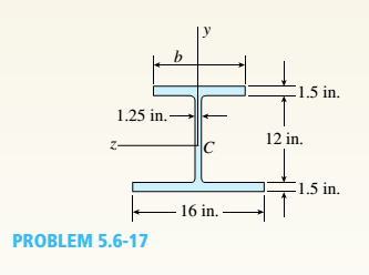
A beam having a cross section in the form of an un symmetric wide-flange shape (sec figure) is subjected to a negative bending moment acting about the 2 axis.
Determine the width b of the top flange in order that the stresses at the top and bottom of the beam will be in the ratio 4:3, respectively.
Expert Solution & Answer

Trending nowThis is a popular solution!

Students have asked these similar questions
A punch press with flywheel adequate to minimize speed fluctuation produces 120 punching strokes per minute, each providing an average force of 2000 N over a stroke of 50 mm. The press is driven through a gear reducer by a shaft rotating 200 rpm. Overall efficiency is 80%. a) What power (W) is transmitted through the shaft? b) What average torque is applied to the shaft?
1.58 The crankshaft of a single-cylinder air compressor rotates 1800 rpm. The piston area is 2000 mm2 and the piston stroke is 50 mm. Assume a simple “idealized” case where the average gas pressure acting on the piston during the compression stroke is 1 MPa, and pressure during the intake stroke is negligible. The compressor is 80% efficient. A flywheel provides adequate control of the speed fluctuation. a) What motor power (kW) is required to drive the crankshaft? b) What torque is transmitted through the crankshaft?
28. The shaft shown in Figure P5-28 is supported by bear-
ings at each end, which have bores of 20.0 mm. Design
the shaft to carry the given load if it is steady and the
shaft is stationary. Make the dimension a as large as pos-
sible while keeping the stress safe. Determine the required
d
20 mm
5.4 kN
d
D = ?
Length not
to scale
-α =
=
-125 mm
20 mm
a =
-250 mm-
FIGURE P5-28 (Problems 28, 29, and 30)
Chapter 5 Solutions
Bundle: Mechanics Of Materials, Loose-leaf Version, 9th + Mindtap Engineering, 1 Term (6 Months) Printed Access Card
Ch. 5 - A steel wire with a diameter of d = 1/16 in. is...Ch. 5 - A copper wire having a diameter ofd = 4 mm is bent...Ch. 5 - A 4.75-in, outside diameter polyethylene pipe...Ch. 5 - A cantilever beam AB is loaded by a couple M0at...Ch. 5 - A thin strip of steel with a length of L =19 in....Ch. 5 - A bar of rectangular cross section is loaded and...Ch. 5 - A simply supported beam with a length L = 10 ft...Ch. 5 - A cantilever beam is subjected to a concentrated...Ch. 5 - A thin strip of hard copper (E = 16,000 ksi)...Ch. 5 - A steel wire (E = 200 GPa) of a diameter d = L25...
Ch. 5 - A thin, high-strength steel rule (E = 30 x 10ft...Ch. 5 - A simply supported wood beam AB with a span length...Ch. 5 - Beam ABC has simple supports at A and B and an...Ch. 5 - A simply supported beam is subjected to a in early...Ch. 5 - Each girder of the lift bridge (sec figure) is 180...Ch. 5 - A freight-car axle AS is loaded approximately as...Ch. 5 - A seesaw weighing 3 lb/ft of length is occupied by...Ch. 5 - During construction of a highway bridge, the main...Ch. 5 - The horizontal beam ABC of an oil-well pump has...Ch. 5 - A railroad tie (or sleeper) is subjected to two...Ch. 5 - A fiberglass pipe is lifted by a sling, as shown...Ch. 5 - A small dam of height h = 2.0 m is constructed of...Ch. 5 - Determine the maximum tensile stress (7, (due to...Ch. 5 - Determine the maximum bending stress emaxdue to...Ch. 5 - A simple beam A B of a span length L = 24 ft is...Ch. 5 - Determine the maximum tensile stress erand maximum...Ch. 5 - A cantilever beam A3, loaded by a uniform load and...Ch. 5 - A canti lever beam A B of a n isosceles t...Ch. 5 - A cantilever beam, a C12 x 30 section, is...Ch. 5 - A frame ABC travels horizontally with an...Ch. 5 - A beam ABC with an overhang from B to C supports a...Ch. 5 - A cantilever beam AB with a rectangular cross...Ch. 5 - A beam with a T-section is supported and loaded as...Ch. 5 - Consider the compound beam with segments AB and...Ch. 5 - A small dam of a height h = 6 ft is constructed of...Ch. 5 - A foot bridge on a hiking trail is constructed...Ch. 5 - A steel post (E=30×106) having thickness t = 1/8...Ch. 5 - Beam ABCDE has a moment release just right of...Ch. 5 - A simply supported wood beam having a span length...Ch. 5 - A simply supported beam (L = 4.5 m) must support...Ch. 5 - The cross section of a narrow-gage railway bridge...Ch. 5 - A fiberglass bracket A BCD with a solid circular...Ch. 5 - A cantilever beanie B is loaded by a uniform load...Ch. 5 - A simple beam of length L = 5 m carries a uniform...Ch. 5 - A simple beam AB is loaded as shown in the figure....Ch. 5 - A pontoon bridge (see figure) is constructed of...Ch. 5 - A floor system in a small building consists of...Ch. 5 - The wood joists supporting a plank Floor (see...Ch. 5 - A beam ABC with an overhang from B to C is...Ch. 5 - -12 A "trapeze bar" in a hospital room provides a...Ch. 5 - A two-axle carriage that is part of an over head...Ch. 5 - A cantilever beam AB with a circular cross section...Ch. 5 - A propped cantilever beam A BC (see figure) has a...Ch. 5 - A small balcony constructed of wood is supported...Ch. 5 - A beam having a cross section in the form of an un...Ch. 5 - A beam having a cross section in the form of a...Ch. 5 - Determine the ratios of the weights of four beams...Ch. 5 - Prob. 5.6.20PCh. 5 - A steel plate (called a cover ploie) having...Ch. 5 - A steel beam ABC is simply supported at A and...Ch. 5 - A retaining wall 6 ft high is constructed of...Ch. 5 - A retaining wall (Fig. a) is constructed using...Ch. 5 - A beam of square cross section (a = length of each...Ch. 5 - The cross section of a rectangular beam having a...Ch. 5 - A tapered cantilever beam A B of length L has...Ch. 5 - .2 A ligmio.irc ii supported by two vorlical beams...Ch. 5 - Prob. 5.7.3PCh. 5 - Prob. 5.7.4PCh. 5 - Prob. 5.7.5PCh. 5 - A cantilever beam AB with rectangular cross...Ch. 5 - A simple beam ABC having rectangular cross...Ch. 5 - A cantilever beam AB having rectangular cross...Ch. 5 - The shear stresses t in a rectangular beam arc...Ch. 5 - .2 Calculate the maximum shear stress tmaxand the...Ch. 5 - A simply supported wood beam is subjected to...Ch. 5 - A simply supported wood beam with overhang is...Ch. 5 - Two wood beams, each of rectangular cross section...Ch. 5 - A cantilever beam of length L = 2 m supports a...Ch. 5 - A steel beam of length L = 16 in. and...Ch. 5 - A beam of rectangular cross section (width/) and...Ch. 5 - A laminated wood beam on simple supports (figure...Ch. 5 - A laminated plastic beam of square cross section...Ch. 5 - A wood beam AB on simple supports with span length...Ch. 5 - A simply supported wood beam of rectangular cross...Ch. 5 - A square wood platform is 8 ft × 8 ft in area and...Ch. 5 - A wood beam ABC with simple supports at A and B...Ch. 5 - A wood pole with a solid circular cross section (d...Ch. 5 - A simple log bridge in a remote area consists of...Ch. 5 - A vertical pole consisting of a circular tube of...Ch. 5 - A circular pole is subjected to linearly varying...Ch. 5 - A sign for an automobile service station is...Ch. 5 - A steel pipe is subjected to a quadratic...Ch. 5 - -1 through 5.10-6 A wide-flange beam (see figure)...Ch. 5 - -1 through 5.10-6 A wide-flange beam (see figure)...Ch. 5 - -1 through 5.10-6 A wide-flange beam (see figure)...Ch. 5 - -1 through 5.10-6 A wide-flange beam (see figure)...Ch. 5 - -1 through 5.10-6 A wide-flange beam (see figure)...Ch. 5 - -1 through 5.10-6 A wide-flange beam (see figure)...Ch. 5 - A cantilever beam AB of length L = 6.5 ft supports...Ch. 5 - A bridge girder A B on a simple span of length L =...Ch. 5 - A simple beam with an overhang supports a uniform...Ch. 5 - A hollow steel box beam has the rectangular cross...Ch. 5 - A hollow aluminum box beam has the square cross...Ch. 5 - The T-beam shown in the figure has cross-sectional...Ch. 5 - Calculate the maximum shear stress tmax. in the...Ch. 5 - A prefabricated wood I-beam serving as a floor...Ch. 5 - A welded steel gird crhaving the erass section...Ch. 5 - A welded steel girder having the cross section...Ch. 5 - A wood box beam is constructed of two 260 mm × 50...Ch. 5 - A box beam is constructed of four wood boards as...Ch. 5 - Two wood box beams (beams A and B) have the same...Ch. 5 - A hollow wood beam with plywood webs has the...Ch. 5 - A beam of a T cross section is formed by nailing...Ch. 5 - The T-beam shown in the figure is fabricated by...Ch. 5 - A steel beam is built up from a W 410 × 85 wide...Ch. 5 - The three beams shown have approximately the same...Ch. 5 - Two W 310 × 74 Steel wide-flange beams are bolted...Ch. 5 - A pole is fixed at the base and is subjected to a...Ch. 5 - A solid circular pole is subjected to linearly...Ch. 5 - While drilling a hole with a brace and bit, you...Ch. 5 - An aluminum pole for a street light weighs 4600 N...Ch. 5 - A curved bar ABC having a circular axis (radius r...Ch. 5 - A rigid Trame ABC is formed by welding two steel...Ch. 5 - A palm tree weighing 1000 lb is inclined at an...Ch. 5 - A vertical pole of aluminum is fixed at the base...Ch. 5 - Because of foundation settlement, a circular tower...Ch. 5 - A steel bracket of solid circular cross section is...Ch. 5 - A cylindrical brick chimney of height H weighs w =...Ch. 5 - A flying but tress transmit s a load P = 25 kN,...Ch. 5 - A plain concrete wall (i.e., a wall with no steel...Ch. 5 - A circular post, a rectangular post, and a post of...Ch. 5 - Two cables, each carrying a tensile force P = 1200...Ch. 5 - Prob. 5.12.16PCh. 5 - A short column constructed of a W 12 × 35...Ch. 5 - A short column with a wide-flange shape is...Ch. 5 - A tension member constructed of an L inch angle...Ch. 5 - A short length of a C 200 × 17.1 channel is...Ch. 5 - The beams shown in the figure are subjected to...Ch. 5 - The beams shown in the figure are subjected to...Ch. 5 - A rectangular beam with semicircular notches, as...Ch. 5 - A rectangular beam with semicircular notches, as...Ch. 5 - A rectangular beam with notches and a hole (see...
Knowledge Booster


Learn more about
Need a deep-dive on the concept behind this application? Look no further. Learn more about this topic, mechanical-engineering and related others by exploring similar questions and additional content below.Similar questions
- The motor shown operates at constant speed and develops a torque of 100 lb-in during normal operation. Attached to the motor shaft is a gear reducer of ratio 5:1, that is, the reducer output shaft rotates in the same direction as the motor but at one-fifth motor speed. Rotation of the reducer housing is prevented by the "torque arm" pin-connected at each end as shown. The reducer output shaft drives the load through a flexible coupling. Neglecting gravity and friction, what loads are applied to (a) the torque arm, (b) the motor output shaft, and (c) the reducer output shaft? Motor Gear reducer Flexible coupling (To load) Torque arm- Torque arm Reducer output shaft Motor Reducer Shaft rotationarrow_forwardPlease can you help with ten attatched question?arrow_forwardAn AISI 1018 steel ball with 1.100-in diameter is used as a roller between a flat plate made from 2024 T3 aluminum and a flat table surface made from ASTM No. 30 gray cast iron. Determine the maximum amount of weight that can be stacked on the aluminum plate without exceeding a maximum shear stress of 19.00 kpsi in any of the three pieces. Assume the figure given below, which is based on a typical Poisson's ratio of 0.3, is applicable to estimate the depth at which the maximum shear stress occurs for these materials. 1.0 0.8 Ratio of stress to Pmax 0.4 90 0.6 στ Tmax 0.2 0.5a a 1.5a 2a 2.5a За Distance from contact surface The maximum amount of weight that can be stacked on the aluminum plate is lbf.arrow_forward
- A carbon steel ball with 27.00-mm diameter is pressed together with an aluminum ball with a 36.00-mm diameter by a force of 11.00 N. Determine the maximum shear stress and the depth at which it will occur for the aluminum ball. Assume the figure given below, which is based on a typical Poisson's ratio of 0.3, is applicable to estimate the depth at which the maximum shear stress occurs for these materials. 1.0 0.8 Ratio of stress to Pma 9 0.6 στ 24 0.4 Tmax 0.2 0 0.5a a 1.5a Z 2a 2.5a За Distance from contact surface The maximum shear stress is determined to be MPa. The depth in the aluminum ball at which the maximum shear stress will occur is determined to be [ mm.arrow_forwardShow all work pleasearrow_forwardDraw top, side, front view With pen(cil) and paper Multi view drawing and handwriting all of itarrow_forward
- A wheel of diameter 150.0 mm and width 37.00 mm carrying a load 2.200 kN rolls on a flat rail. Take the wheel material as steel and the rail material as cast iron. Assume the figure given, which is based on a Poisson's ratio of 0.3, is applicable to estimate the depth at which the maximum shear stress occurs for these materials. At this critical depth, calculate the Hertzian stresses σr, σy, σz, and Tmax for the wheel. 1.0 0.8 0, т Ratio of stress to Pmax 0.4 0.6 90 69 0.2 0.5b b 1.5b Tmax 2b Distance from contact surface The Hertizian stresses are as follows: 02 = or = -23.8 psi for the wheel =| necessary.) σy for the wheel =| MPa σz for the wheel = MPa V4 for the wheel = | MPa 2.5b ཡི 3b MPa (Include a minus sign ifarrow_forwardOnly question 3arrow_forwardOnly question 2arrow_forward
- Solve for the support reactions at A and B. C 3 kN/m B -1.5 m- -1.5 m 1.5 m- 1.5 m-arrow_forward4. Solve for the support reactions at A and B. W1 600 lb/ft W2 150 lb/ft A Barrow_forwardIn cold isostatic pressing, the mold is most typically made of which one of the following: thermosetting polymer tool steel sheet metal textile rubberarrow_forward
arrow_back_ios
SEE MORE QUESTIONS
arrow_forward_ios
Recommended textbooks for you
 Mechanics of Materials (MindTap Course List)Mechanical EngineeringISBN:9781337093347Author:Barry J. Goodno, James M. GerePublisher:Cengage Learning
Mechanics of Materials (MindTap Course List)
Mechanical Engineering
ISBN:9781337093347
Author:Barry J. Goodno, James M. Gere
Publisher:Cengage Learning
Mechanics of Materials Lecture: Beam Design; Author: UWMC Engineering;https://www.youtube.com/watch?v=-wVs5pvQPm4;License: Standard Youtube License