.2 A ligmio.irc ii supported by two vorlical beams consistins: of thin-walled, tapered circular lubes (see ligure part at. for purposes of this analysis, each beam may be represented as a cantilever AB of length L = 8.0 m subjected to a lateral load P = 2.4 kN at the free end. The tubes have a constant thickness ; = 10.0 mm and average diameters d A = 90 mm and dB = 270 mm at ends A and B, re s pec lively. Because the thickness is small compared to the diameters, the moment of inerlia at any cross section may be obtained from the formula / = jrrf3;/8 (see Case 22, Appendix E); therefore, the section modulus mav be obtained from the formula S = trdhl A . (a) At what dislance A from the free end docs the maximum bending stress occur? What is the magnitude trllul of the maximum bending stress? What is the ratio of the maximum stress to the largest stress (b) Repeat part (a) if concentrated load P is applied upward at A and downward uniform load q {-x) = 2PIL is applied over the entire beam as shown in the figure part b What is the ratio of the maximum stress to the stress at the location of maximum moment?
.2 A ligmio.irc ii supported by two vorlical beams consistins: of thin-walled, tapered circular lubes (see ligure part at. for purposes of this analysis, each beam may be represented as a cantilever AB of length L = 8.0 m subjected to a lateral load P = 2.4 kN at the free end. The tubes have a constant thickness ; = 10.0 mm and average diameters d A = 90 mm and dB = 270 mm at ends A and B, re s pec lively. Because the thickness is small compared to the diameters, the moment of inerlia at any cross section may be obtained from the formula / = jrrf3;/8 (see Case 22, Appendix E); therefore, the section modulus mav be obtained from the formula S = trdhl A . (a) At what dislance A from the free end docs the maximum bending stress occur? What is the magnitude trllul of the maximum bending stress? What is the ratio of the maximum stress to the largest stress (b) Repeat part (a) if concentrated load P is applied upward at A and downward uniform load q {-x) = 2PIL is applied over the entire beam as shown in the figure part b What is the ratio of the maximum stress to the stress at the location of maximum moment?
Solution Summary: The author calculates the maximum bending stress in case of the tapered cantilever beam.
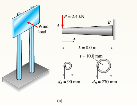
.2 A ligmio.irc ii supported by two vorlical beams consistins: of thin-walled, tapered circular lubes (see ligure part at. for purposes of this analysis, each beam may be represented as a cantilever AB of length L = 8.0 m subjected to a lateral load P = 2.4 kN at the free end. The tubes have a constant thickness ; = 10.0 mm and average diameters dA = 90 mm and dB = 270 mm at ends A and B, re s pec lively.
Because the thickness is small compared to the diameters, the moment of inerlia at any cross section may be obtained from the formula / = jrrf3;/8 (see Case 22, Appendix E); therefore, the section modulus mav be obtained from the formula S = trdhlA.
(a) At what dislance A from the free end docs the maximum bending stress occur? What is the magnitude trllul of the maximum bending stress? What is the ratio of the maximum stress to the largest stress
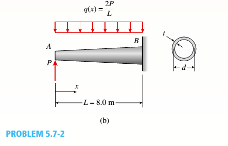
(b) Repeat part (a) if concentrated load P is applied upward at A and downward uniform load q {-x) = 2PIL is applied over the entire beam as shown in the figure part b What is the ratio of the maximum stress to the stress at the location of maximum moment?
The state of stress at a point is σ = -4.00 kpsi, σy = 16.00 kpsi, σ = -14.00 kpsi, Try = 11.00 kpsi,
Tyz = 8.000 kpsi, and T = -14.00 kpsi.
Determine the principal stresses.
The principal normal stress σ₁ is determined to be [
The principal normal stress σ2 is determined to be [
The principal normal stress σ3 is determined to be
kpsi.
kpsi.
The principal shear stress 71/2 is determined to be [
The principal shear stress 7½ is determined to be [
The principal shear stress T₁/, is determined to be [
kpsi.
kpsi.
kpsi.
kpsi.
Repeat Problem 28, except using a shaft that is rotatingand transmitting a torque of 150 N * m from the left bearing to the middle of the shaft. Also, there is a profile keyseat at the middle under the load.
(I want to understand this problem)
Prob 2.
The material distorts into the dashed position
shown. Determine the average normal strains &x, Ey
and the shear strain Yxy at A, and the average
normal strain along line BE.
50 mm
B
200 mm
15 mm
30 mm
D
ΕΙ
50 mm
x
A
150 mm
F
Chapter 5 Solutions
Bundle: Mechanics Of Materials, Loose-leaf Version, 9th + Mindtap Engineering, 1 Term (6 Months) Printed Access Card
Need a deep-dive on the concept behind this application? Look no further. Learn more about this topic, mechanical-engineering and related others by exploring similar questions and additional content below.


 Mechanics of Materials (MindTap Course List)Mechanical EngineeringISBN:9781337093347Author:Barry J. Goodno, James M. GerePublisher:Cengage Learning