
Concept explainers
Videos
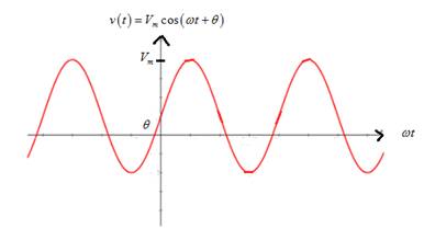
Consider the plot of the sinusoidal voltage
- Stretches the sinusoidal curve vertically.
Which statement best describes
b. Increasing the frequency f?
c. Decreasing
d. Decreasing the angular frequency w?
e. Increasing the period?
(a)
Change in sinusoidal voltage graph if peak amplitude is increased.
Answer to Problem 5.1P
Increasing the peak amplitude stretches the sinusoidal curve vertically.
Option (1).
Explanation of Solution
Given information:
Given sinusoidal voltage is
Calculation:
Graph of sinusoidal voltage is
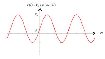
From the graph, it is noted thatif peak amplitude Vm is increased, it stretches the sinusoidal curve vertically.
(b)
Change in sinusoidal voltage graph if frequency is increased.
Answer to Problem 5.1P
Increasing the frequency compresses the sinusoidal curve horizontally.
Option (4).
Explanation of Solution
Given information:
Given sinusoidal voltage is
Calculation:
Graph of sinusoidal voltage is

From the graph, it is noted that if the frequency is increased,the time period is reduced so that it compresses the sinusoidal curve horizontally.
(c)
Change in sinusoidal voltage graph if phase angle (theta) is decreased.
Answer to Problem 5.1P
Decreasing the phase angle (theta) translates the sinusoidal curve to the right.
Option (5).
Explanation of Solution
Given information:
Given sinusoidal voltage is
Calculation:
Graph of sinusoidal voltage is

From the graph, it is noted that if the phase angle (theta) is decreased, it translates the sinusoidal curve to the right.
(d)
Change in sinusoidal voltage graph if the angular frequency is decreased.
Answer to Problem 5.1P
Decreasing the angular frequency stretches the sinusoidal voltage graph horizontally.
Option (3).
Explanation of Solution
Given information:
Given sinusoidal voltage is
Calculation:
Graph of sinusoidal voltage is
From the graph, it is noted that if the angular frequency is decreased, it increases the time period of the curve,which means it stretches sinusoidal horizontally.
(e)
Change in sinusoidal voltage graph if the time period is increased.
Answer to Problem 5.1P
Increasing the time period stretches the sinusoidal voltage graph horizontally.
Option (3).
Explanation of Solution
Given information:
Given sinusoidal voltage is
Calculation:
Graph of sinusoidal voltage is

From the graph, it is noted that if time period is increased, it stretches the sinusoidal voltage graph horizontally.
Want to see more full solutions like this?
Chapter 5 Solutions
Electrical Engineering: Principles & Applications (7th Edition)
Additional Engineering Textbook Solutions
Elementary Surveying: An Introduction To Geomatics (15th Edition)
Computer Science: An Overview (13th Edition) (What's New in Computer Science)
Degarmo's Materials And Processes In Manufacturing
Mechanics of Materials (10th Edition)
Introduction To Programming Using Visual Basic (11th Edition)
Java: An Introduction to Problem Solving and Programming (8th Edition)


- Choose the correct answer to the following questions: 1- What is the total power radiated in Watts for the power density W = a) 4π² b) 8m²/3 2- Fresnel zone is also called as sine W/m²? 3r² c) 4π²/3 d) 2π²/3 a) Near Field b) Far Field c) Electrostatic Field d) Reactive Field 3- The far-field distance at 900 MHz, if the maximum antenna dimension is 0.75 m is.... a) 3.375 m b) 3.5m c) 3.375 cm d) none 4- The antenna gain is on input power to antenna and on power due to ohmic losses. c) Independent, dependent d) a) Independent, independent b) Dependent, independent Dependent, dependent 5- If beam width of the antenna increases, then directivity. a) Decreases b) Increases c) Remains unchanged d) Depends on type of antennaarrow_forwardplease solve this and clarify each step. thanksarrow_forwardThe input reactance of 1/2 dipole with radius of 1/30 is given as shown in figure below, Assuming the wire of dipole is conductor 5.6*107 S/m, determine at f=1 GHz the a- Loss resistance, b- Radiation efficiency c- Reflection efficiency when the antenna is connected to T.L shown in the figure. Rr Ro= 50 2 Avg/4 RL -j100 [In(l/a) 1.5] tan(ẞ1)arrow_forward
- Find Zeq here. i already had one solution written to me but it's wrong. my main question is. i know that i do the parallel connection first so 2x2 / 2+2 = 1ohm but what i'm asking is since it's an open terminal is R3,2(parallel resistors) in series to R1? or should i first do R3,2 // to ZL and then add R1 in series? PLEASE READ THIS. and solve properly. EXPLAIN WHAT I ASKED PROPERLY. UPVOTE WILL BE GIVEN.arrow_forwardThe E-field pattern of an antenna, independent of o, varies as follows: E = 0 7100 0° ≤0≤45° 45° < 0 ≤ 90° 90° < 0 ≤ 180° (a) What is the directivity of this antenna? (b) What is the radiation resistance of the antenna at 200 m from it if the field is equal to 10 V/m (rms) for 0 = 0° at that distance and the terminal current is 5 A (rms)?arrow_forwardFind Zeq here. i already had one solution written to me but it's wrong. my main question is. i know that i do the parallel connection first so 2x2 / 2+2 = 1ohm but what i'm asking is since it's an open terminal is R3,2(parallel resistors) in series to R1? or should i first do R3,2 // to ZL and then add R1 in series? PLEASE READ THIS. and solve properly. EXPLAIN WHAT I ASKED PROPERLY. UPVOTE WILL BE GIVEN.arrow_forward
- Find Zeq here, ignore the semi circle in the wiring i'm just bad at drawing circuits. ZL=JWL write Zeq in terms of JW and give me the final equation. (basically check the parallel and series combinations and give me the final answer.)Will upvote correct answer. Thanks!arrow_forwardFill in the chart and answer questions Answer problems 10, 11, and 12 using the following information:An addition is being planned to a school building. You have been asked to determine theload that will be added to the panelboard that will serve this addition.The addition will be a building 80 ft 3 50 ft. It will consist of four classrooms, every40 ft 3 20 ft and a corridor that is 10-ft wide The following loads will be installed:Each classroom:12 fluorescent luminaires, 2 ft 3 4 ft @ 85 VA each20 duplex receptaclesAC unit, 208-volt, 1-phase @ 5000 VACorridor:5 fluorescent luminaires, 1 ft 3 8 ft @ 85 VA each8 duplex receptaclesExterior:4 wall-mounted luminaires @ 125 VA each4 duplex receptacles 10. The calculated load is__________ VA.11. The connected load is__________ VA.12. The neutral load is_____________ VA.arrow_forwardA 1200-ampere service was installed, consisting of three sets of 600 kcmil THHN/THWN copper conductors per phase. The electrical contractor was careful to cut theconductors the same length. When the utility crew made up the connections at theservice heads, they cut the conductors to different lengths to make their connectionssimpler. The actual lengths of the service-entrance conductors in a given phase ended up being20 ft (6.1 m), 22 ft (6.7 m), and 24 ft (7.3 m). The maximum ampacity of a 600-kcmilTHHN/THWN copper conductor is 420 amperes using the 75°C column of Table310.16. This is more than adequate for the calculated 1200 amperes when three conductors are run in parallel. Determine how the load of 1200 amperes would divide in each of the three paralleledconductors in a phase.arrow_forward
- Determine the conductor sizes for a feeder to a panelboard. It is a 120/240-volt,single-phase system. The OCPD has a rating of 100 amperes. The calculated load is15,600 VA. All the loads are 120 volts.arrow_forwardCalculate the neutral current in a 120/240-volt, single-phase system when the current inphase A is 20 amperes and the current in phase B is 40 amperes. The load is resistive. Calculate the neutral current in a 208Y/120-volt, 3-phase, 4-wire system when thecurrent in phase A is 0, in phase B is 40, and in phase C is 60 amperes. The load isresistivearrow_forwardCalculate the neutral current in a 208Y/120-volt, 3-phase, 4-wire system when the current in phase A is 20, in phase B is 40, and in phase C is 60 amperes. The load is resistive.arrow_forward
 Introductory Circuit Analysis (13th Edition)Electrical EngineeringISBN:9780133923605Author:Robert L. BoylestadPublisher:PEARSON
 Delmar's Standard Textbook Of ElectricityElectrical EngineeringISBN:9781337900348Author:Stephen L. HermanPublisher:Cengage Learning
 Programmable Logic ControllersElectrical EngineeringISBN:9780073373843Author:Frank D. PetruzellaPublisher:McGraw-Hill Education
 Fundamentals of Electric CircuitsElectrical EngineeringISBN:9780078028229Author:Charles K Alexander, Matthew SadikuPublisher:McGraw-Hill Education
 Electric Circuits. (11th Edition)Electrical EngineeringISBN:9780134746968Author:James W. Nilsson, Susan RiedelPublisher:PEARSON
 Engineering ElectromagneticsElectrical EngineeringISBN:9780078028151Author:Hayt, William H. (william Hart), Jr, BUCK, John A.Publisher:Mcgraw-hill Education,