
Electrical Engineering: Principles & Applications (7th Edition)
7th Edition
ISBN: 9780134484143
Author: Allan R. Hambley
Publisher: PEARSON
expand_more
expand_more
format_list_bulleted
Concept explainers
Videos
Textbook Question
Chapter 5, Problem 5.81P
Two loads. A and B, are connected in parallel across a 1-kV-rms 60-Hz line, as shown in Figure P5.81. Load A consumes 10 kW with a 90 percent lagging power facto. Load B has an apparent power of 15 ICVA with an 80 percent lagging power factor. Find the power, reactive power, and apparent power delivered by the source. What is the power factor seen by the source?
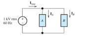
Figure P5.81
Expert Solution & Answer
Want to see the full answer?
Check out a sample textbook solution
Students have asked these similar questions
General Directions: Read the questions carefully and answer (3*10=30marks)
1. Design a summing amplifier by choosing appropriate values of resistors an so that
the output is 5 times the sum of the input voltages. (you are free to use any number
of inputs, the type of op-amp, any value of resistors)
2. Derive the equation for the closed loop gain of the inverting and non-inverting
Amplifier using appropriate circuit diagrams.
3. Determine the values read by the measuring devices using appropriate formulae
www
Voc
+8V
R₁
33 k
Rc
2.2 k
ww
WWW
Poc 200
R₁₂
RE
10 kn
1.0 kn
十
: + B
日
العنوان
I need a detailed drawing with explanation
ややハメPV+96252
4
Project Homework:
Create a simulation for a tank when the flowrate inside and outside the tank must
range between 0 and 10 lit/s:
1) The level should be controlled within a range between more than zero to 1000
lit.
2) An alarm must be launched when the level is out of range (less than 100 and
more than 900 lit).
3) When the capacity reaches to the maximum the motor turns OFF.
area=A
Qout
-20
solve in lab view
X9.01
*175*1
Project Homework:
Create a simulation for a tank when the flowrate inside and outside the tank must
range between 0 and 10 lit/s:
1) The level should be controlled within a range between more than zero to 1000
lit.
2) An alarm must be launched when the level is out of range (less than 100 and
more than 900 lit).
3) When the capacity reaches to the maximum the motor turns OFF.
Qin
h
C
Qout
area=A
solve in lab view
Chapter 5 Solutions
Electrical Engineering: Principles & Applications (7th Edition)
Ch. 5 - Consider the plot of the sinusoidal voltage...Ch. 5 - Repeat Problem P5.3 for v(t) = 50 sin (500t+120) .Ch. 5 - A sinusoidal voltage v(t) has an rms value of 20...Ch. 5 - A current i(t)=10cos(2000t) flows through a 100...Ch. 5 - We have a voltage v(t)=1000sin(500t) across a 500...Ch. 5 - Calculate the rms value of the half-wave rectified...Ch. 5 - We have v1(t)=10cos(t+30) . The current i1(t)has...Ch. 5 - Solve for the mesh currents shown in Figure P5.55.Ch. 5 - Two loads. A and B, are connected in parallel...
Knowledge Booster


Learn more about
Need a deep-dive on the concept behind this application? Look no further. Learn more about this topic, electrical-engineering and related others by exploring similar questions and additional content below.Similar questions
- QUESTION [3] A no-load and short-circuit test should be conducted on a 220V/110V, 280VA transformer. a. Draw the circuit diagram for the no-load test and include all measurements that should be made. Also write down the maximum voltage that you should apply to the primary winding and estimate the current drawn from the supply. (5) b. Draw a circuit diagram for the short-circuit test and include all measurements that should be made. Also write down the maximum current that should be allowed to flow in the primary winding and estimated the primary voltage that will cause this value of the current to flow. (5)arrow_forwardOnly expert should solve it pleasearrow_forwardNeed handwritten solution pleasearrow_forward
- Design a lowpass FIR filter using frequency sampling technique having cut-off frequency of T/2 rad/sample. The filter should have linear phase and length of 17.arrow_forwardA dc compound motor having a rating of 10 kW, 1150 r/min, 230 V, 50 A, has the following losses at full-load: bearing friction loss 40 W brush friction loss == 50 W windage loss = 200 W (1) total mechanical losses = 290 W (2) iron losses = 420 W (3) copper loss in the shunt field = 120 W copper losses at full-load: (4) a. in the armature b. in the series field c. in the commutating winding total copper loss in the 500 W 25 W 70 W armature circuit at full-load = 595 Warrow_forward4 What determines the power rating of a ma- chine? -5 If we cover up the vents in a motor, its out- put power must be reduced. Explain. -6 If a motor operates in a cold environment, may we load it above its rated power? Why?arrow_forward
- An electric motor driving a skip hoist with- draws 1.5 metric tons of minerals from a trench 20 m deep every 30 seconds. If the hoist has an overall efficiency of 94 percent, calculate the power output of the motor in horsepower and in kilowatts.arrow_forwardThe efficiency of a motor is always low when it operates at 10 percent of its nominal power rating. Explain.arrow_forwardA dc motor connected to a 240 V line pro- duces a mechanical output of 160 hp. Knowing that the losses are 12 kW, calculate the input power and the line current.arrow_forward
- A 115 V dc generator delivers 120 A to a load. If the generator has an efficiency of 81 percent, calculate the mechanical power needed to drive it [hp].arrow_forwardA machine having class B insulation attains a temperature of 208°C (by resistance) in a torrid ambient temperature of 180°C. a. What is the temperature rise? b. Is the machine running too hot and, if so, by how much?arrow_forward1 Name the losses in a dc motor. 2 What causes iron losses and how can they be reduced? -3 Explain why the temperature of a machine increases as the load increases.arrow_forward
arrow_back_ios
SEE MORE QUESTIONS
arrow_forward_ios
Recommended textbooks for you
 Power System Analysis and Design (MindTap Course ...Electrical EngineeringISBN:9781305632134Author:J. Duncan Glover, Thomas Overbye, Mulukutla S. SarmaPublisher:Cengage Learning
Power System Analysis and Design (MindTap Course ...
Electrical Engineering
ISBN:9781305632134
Author:J. Duncan Glover, Thomas Overbye, Mulukutla S. Sarma
Publisher:Cengage Learning
What is the Difference Between Single Phase and Three Phase???; Author: Electrician U;https://www.youtube.com/watch?v=FEydcr4wJw0;License: Standard Youtube License