EBK FUNDAMENTALS OF APPLIED ELECTROMAGN
7th Edition
ISBN: 8220100663659
Author: ULABY
Publisher: PEARSON
expand_more
expand_more
format_list_bulleted
Textbook Question
Chapter 5, Problem 41P
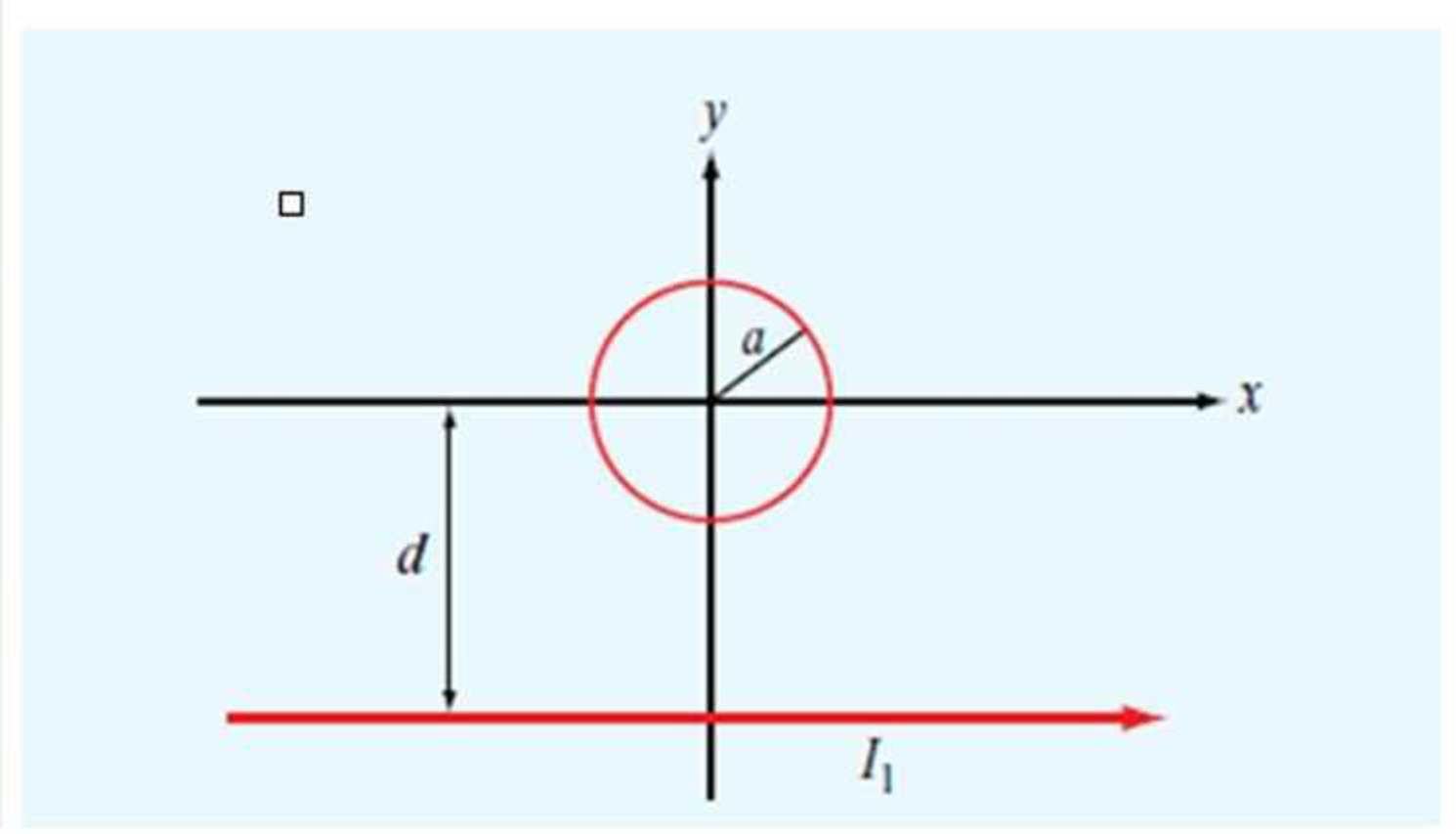
Determine the mutual inductance between the circular loop and the linear current shown in Fig. P5.41.

Expert Solution & Answer
Want to see the full answer?
Check out a sample textbook solution
Students have asked these similar questions
A dc compound motor having a rating of 10 kW,
1150 r/min, 230 V, 50 A, has the following losses at
full-load:
bearing friction loss
40 W
brush friction loss
==
50 W
windage loss
=
200 W
(1)
total mechanical losses
=
290 W
(2)
iron losses
=
420 W
(3)
copper loss in the shunt field
=
120 W
copper losses at full-load:
(4)
a. in the armature
b. in the series field
c. in the commutating winding
total copper loss in the
500 W
25 W
70 W
armature circuit at full-load
=
595 W
4 What determines the power rating of a ma-
chine?
-5 If we cover up the vents in a motor, its out-
put power must be reduced. Explain.
-6 If a motor operates in a cold environment,
may we load it above its rated power? Why?
An electric motor driving a skip hoist with-
draws 1.5 metric tons of minerals from a
trench 20 m deep every 30 seconds. If the
hoist has an overall efficiency of 94 percent,
calculate the power output of the motor in
horsepower and in kilowatts.
Chapter 5 Solutions
EBK FUNDAMENTALS OF APPLIED ELECTROMAGN
Ch. 5.1 - What are the major differences between the...Ch. 5.1 - Prob. 2CQCh. 5.1 - How is the direction of the magnetic moment of a...Ch. 5.1 - If one of two wires of equal length is formed into...Ch. 5.1 - An electron moving in the positive x direction...Ch. 5.1 - A proton moving with a speed of 2 106 m/s through...Ch. 5.1 - A charged particle with velocity u is moving in a...Ch. 5.1 - A horizontal wire with a mass per unit length of...Ch. 5.1 - A square coil of 100 turns and 0.5 m long sides is...Ch. 5.2 - Two infinitely long parallel wires carry currents...
Ch. 5.2 - Devise a right-hand rule for the direction of the...Ch. 5.2 - What is a magnetic dipole? Describe its magnetic...Ch. 5.2 - Prob. 6ECh. 5.2 - A wire carrying a current of 4 A is formed into a...Ch. 5.2 - Prob. 8ECh. 5.3 - What are the fundamental differences between...Ch. 5.3 - Prob. 9CQCh. 5.3 - Compare the utility of applying the BiotSavart law...Ch. 5.3 - Prob. 11CQCh. 5.3 - A current I flows in the inner conductor of a long...Ch. 5.3 - The metal niobium becomes a superconductor with...Ch. 5.5 - What are the three types of magnetic materials and...Ch. 5.5 - What causes magnetic hysteresis in ferromagnetic...Ch. 5.5 - Prob. 14CQCh. 5.5 - The magnetic vector M is the vector sum of the...Ch. 5.6 - With reference to Fig. 5-24, determine the single...Ch. 5.7 - Prob. 15CQCh. 5.7 - What is the difference between self-inductance and...Ch. 5.7 - Prob. 17CQCh. 5.7 - Use Eq. (5.89) to obtain an expression for B at a...Ch. 5 - An electron with a speed of 8 106 m/s is...Ch. 5 - When a particle with charge q and mass m is...Ch. 5 - The circuit shown in Fig. P5.3 uses two identical...Ch. 5 - The rectangular loop shown in Fig. P5.4 consists...Ch. 5 - In a cylindrical coordinate system, a 2 m long...Ch. 5 - Prob. 6PCh. 5 - Prob. 7PCh. 5 - Prob. 8PCh. 5 - The loop shown in Fig. P5.9 consists of radial...Ch. 5 - An infinitely long, thin conducting sheet defined...Ch. 5 - An infinitely long wire carrying a 25 A current in...Ch. 5 - Prob. 12PCh. 5 - Prob. 13PCh. 5 - Prob. 14PCh. 5 - A circular loop of radius a carrying current I1 is...Ch. 5 - Prob. 16PCh. 5 - Prob. 17PCh. 5 - Prob. 18PCh. 5 - Three long, parallel wires are arranged as shown...Ch. 5 - A square loop placed as shown in Fig. P5.20 has 2...Ch. 5 - Prob. 21PCh. 5 - Prob. 22PCh. 5 - Repeat Problem 5.22 for a current density J=zJ0er.Ch. 5 - In a certain conducting region, the magnetic field...Ch. 5 - Prob. 25PCh. 5 - Prob. 26PCh. 5 - Prob. 27PCh. 5 - A uniform current density given by J=zj0 (A/m2)...Ch. 5 - A thin current element extending between z = L/2...Ch. 5 - In the model of the hydrogen atom proposed by Bohr...Ch. 5 - Iron contains 8.5 1028 atoms/m3. At saturation,...Ch. 5 - The xy plane separates two magnetic media with...Ch. 5 - Given that a current sheet with surface current...Ch. 5 - In Fig. P5.34, the plane defined by x y = 1...Ch. 5 - The plane boundary defined by z = 0 separates air...Ch. 5 - Prob. 36PCh. 5 - Prob. 37PCh. 5 - A solenoid with a length of 20 cm and a radius of...Ch. 5 - Prob. 39PCh. 5 - The rectangular loop shown in Fig. P5.40 is...Ch. 5 - Determine the mutual inductance between the...
Knowledge Booster
Learn more about
Need a deep-dive on the concept behind this application? Look no further. Learn more about this topic, electrical-engineering and related others by exploring similar questions and additional content below.Similar questions
- The efficiency of a motor is always low when it operates at 10 percent of its nominal power rating. Explain.arrow_forwardA dc motor connected to a 240 V line pro- duces a mechanical output of 160 hp. Knowing that the losses are 12 kW, calculate the input power and the line current.arrow_forwardA 115 V dc generator delivers 120 A to a load. If the generator has an efficiency of 81 percent, calculate the mechanical power needed to drive it [hp].arrow_forward
- A machine having class B insulation attains a temperature of 208°C (by resistance) in a torrid ambient temperature of 180°C. a. What is the temperature rise? b. Is the machine running too hot and, if so, by how much?arrow_forward1 Name the losses in a dc motor. 2 What causes iron losses and how can they be reduced? -3 Explain why the temperature of a machine increases as the load increases.arrow_forward20. A tractor weighing 14 kN with a wheel base of 3m carries an 8 kN load on its rear wheel. Compute the maximum bending moment and shear when crossing a 4.5 span. Consider the load only at the wheels.arrow_forward
- A 110-V, three-phase, Y-connected, 8 pole, 48-slot, 6000-rpm, double-layer wound chronoun anı vonorotor boo 10 +1 urn or oilarrow_forward-7 Name some of the factors that contribute to the deterioration of organic insulators. -8 A motor is built with class H insulation. What maximum hot-spot temperature can it withstand?arrow_forwardCalculate the full-load current of a 250 hp, 230 V dc motor having an efficiency of 92 percent.arrow_forward
- Assignment #2 A 110-V, three-phase, Y-connected, 8 pole, 48-slot, 6000-rpm, double-layer wound, synchronous generator has 12 turns per coil. If one side of the coil is in slot 1, the other side is in slot 6. There are 4 parallel paths. When the generator delivers the rated load at a line voltage of 110 V, the voltage regulation is 5%. What is the flux per pole? Draw two consecutive phasegroups of one of the phase windings and connect them (a) in series and (b) in parallel showing the Start (S) and Finish (F) of both connections. (A separate drawing for each connection)arrow_forward3-4 Transmissiva Live of 120km has R= 0.2 ~2/15 X= 0.8 -2/km Y = 15H/6 5/km The line is supplies a load of 45 kV, SOMW, 0.8 lead p.f find sending voltage, Sending Current p.f. Sanding Voltage Regulation ⑨Voltage 5 Ⓒ charching coming! изу usy π cct लेarrow_forwardA (medium) single phase transmission line 100 km long has the following constants : Resistance/km = 0.25 Q; Susceptance/km = 14 × 10° siemen ; Reactance/km = 0.8 Receiving end line voltage = 66,000 V Assuming that the total capacitance of the line is localised at the receiving end alone, determine (i) the sending end current (ii) the sending end voltage (iii) regulation and (iv) supply power factor. The line is delivering 15,000 kW at 0.8 power factor Lead Draw the phasor diagram to illustrate your calculations.arrow_forward
arrow_back_ios
SEE MORE QUESTIONS
arrow_forward_ios
Recommended textbooks for you
 Introductory Circuit Analysis (13th Edition)Electrical EngineeringISBN:9780133923605Author:Robert L. BoylestadPublisher:PEARSON
 Delmar's Standard Textbook Of ElectricityElectrical EngineeringISBN:9781337900348Author:Stephen L. HermanPublisher:Cengage Learning
 Programmable Logic ControllersElectrical EngineeringISBN:9780073373843Author:Frank D. PetruzellaPublisher:McGraw-Hill Education
 Fundamentals of Electric CircuitsElectrical EngineeringISBN:9780078028229Author:Charles K Alexander, Matthew SadikuPublisher:McGraw-Hill Education
 Electric Circuits. (11th Edition)Electrical EngineeringISBN:9780134746968Author:James W. Nilsson, Susan RiedelPublisher:PEARSON
 Engineering ElectromagneticsElectrical EngineeringISBN:9780078028151Author:Hayt, William H. (william Hart), Jr, BUCK, John A.Publisher:Mcgraw-hill Education,

Introductory Circuit Analysis (13th Edition)
Electrical Engineering
ISBN:9780133923605
Author:Robert L. Boylestad
Publisher:PEARSON

Delmar's Standard Textbook Of Electricity
Electrical Engineering
ISBN:9781337900348
Author:Stephen L. Herman
Publisher:Cengage Learning

Programmable Logic Controllers
Electrical Engineering
ISBN:9780073373843
Author:Frank D. Petruzella
Publisher:McGraw-Hill Education

Fundamentals of Electric Circuits
Electrical Engineering
ISBN:9780078028229
Author:Charles K Alexander, Matthew Sadiku
Publisher:McGraw-Hill Education

Electric Circuits. (11th Edition)
Electrical Engineering
ISBN:9780134746968
Author:James W. Nilsson, Susan Riedel
Publisher:PEARSON

Engineering Electromagnetics
Electrical Engineering
ISBN:9780078028151
Author:Hayt, William H. (william Hart), Jr, BUCK, John A.
Publisher:Mcgraw-hill Education,
Types of Systems; Author: Neso Academy;https://www.youtube.com/watch?v=IRdDcSO_fQw;License: Standard youtube license