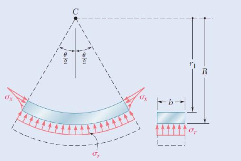
For a curved bar of rectagular cross section subjected to a bending couple M, show that the radial stress at the neutral surface is
and compute the value of σr for the curved bar of Concept Applications 4.10 and 4.11. (Hint: consider the free-body diagram of the portion of the beam located above the neutral suface.)

Fig. P4.191
Want to see the full answer?
Check out a sample textbook solution
Chapter 4 Solutions
Mechanics of Materials, 7th Edition
- A pump delivering 230 lps of water at 30C has a 300-mm diameter suction pipe and a 254-mm diameter discharge pipe as shown in the figure. The suction pipe is 3.5 m long and the discharge pipe is 23 m long, both pipe's materials are cast iron. The water is delivered 16m above the intake water level. Considering head losses in fittings, valves, and major head loss. a) Find the total dynamic head which the pump must supply. b)It the pump mechanical efficiency is 68%, and the motor efficiency is 90%, determine the power rating of the motor in hp.given that: summation of K gate valve = 0.25check valve=390 degree elbow= 0.75foot valve= 0.78arrow_forwardA pump delivering 230 lps of water at 30C has a 300-mm diameter suction pipe and a 254-mm diameter discharge pipe as shown in the figure. The suction pipe is 3.5 m long and the discharge pipe is 23 m long, both pipe's materials are cast iron. The water is delivered 16m above the intake water level. Considering head losses in fittings, valves, and major head loss. a) Find the total dynamic head which the pump must supply. b)It the pump mechanical efficiency is 68%, and the motor efficiency is 90%, determine the power rating of the motor in hp.arrow_forwardThe tensile 0.2 percent offset yield strength of AISI 1137 cold-drawn steel bars up to 1 inch in diameter from 2 mills and 25 heats is reported as follows: Sy 93 95 101 f 97 99 107 109 111 19 25 38 17 12 10 5 4 103 105 4 2 where Sy is the class midpoint in kpsi and fis the number in each class. Presuming the distribution is normal, determine the yield strength exceeded by 99.0% of the population. The yield strength exceeded by 99.0% of the population is kpsi.arrow_forward
- Solve this problem and show all of the workarrow_forwardI tried to go through this problem but I don't know what I'm doing wrong can you help me?arrow_forwardGenerate the kinematic diagram of the following mechanisms using the given symbols. Then, draw their graphs and calculate their degrees of freedom (DoF) using Gruebler's formula. PUNTO 2. PUNTO 3. !!!arrow_forward
- Create a schematic representation of the following mechanisms using the given symbols and draw their graphs. Then, calculate their degrees of freedom (DoF) using Gruebler's formula. PUNTO 6. PUNTO 7.arrow_forwardhow the kinematic diagram of the following mechanisms would be represented using the given symbols? PUNTO 0. PUNTO 1. °arrow_forwardCreate a schematic representation of the following mechanisms using the given symbols and draw their graphs. Then, calculate their degrees of freedom (DOF) using Gruebler's formula. PUNTO 4. PUNTO 5. (0) Groundarrow_forward
- Draw the graph of ALL the mechanisms and calculate their DoF using Gruebler's formula. PUNTO 0. PUNTO 1.arrow_forwardAn adjustable support. Construction designed to carry vertical load and is adjusted by moving the blue attachment vertically. The link is articulated at both ends (free to rotate) and can therefore only transmit power axially. Analytically calculate the force to which the link is subjected? Calculate analytically rated voltage in the middle of the link.? F=20kN Alpha 30 deg Rel 225 Mpans:5arrow_forwardA swivel crane where the load is moved axially along the beam through the wagon to which the hook is attached. Round bar with a diameter of ∅30 mm. The support beam is articulated at both ends (free to rotate) and can therefore only transmit force axially. Calculate reaction force in the x-direction at point A? Calculate analytical reaction force in the y-direction of point A? Calculate nominal stress in the middle of the support beam?Lengt 5 mAlfa 25 degX=1.5mIPE300-steelmass:1000 kgarrow_forward
 Elements Of ElectromagneticsMechanical EngineeringISBN:9780190698614Author:Sadiku, Matthew N. O.Publisher:Oxford University Press
 Mechanics of Materials (10th Edition)Mechanical EngineeringISBN:9780134319650Author:Russell C. HibbelerPublisher:PEARSON
 Thermodynamics: An Engineering ApproachMechanical EngineeringISBN:9781259822674Author:Yunus A. Cengel Dr., Michael A. BolesPublisher:McGraw-Hill Education
 Control Systems EngineeringMechanical EngineeringISBN:9781118170519Author:Norman S. NisePublisher:WILEY
 Mechanics of Materials (MindTap Course List)Mechanical EngineeringISBN:9781337093347Author:Barry J. Goodno, James M. GerePublisher:Cengage Learning
 Engineering Mechanics: StaticsMechanical EngineeringISBN:9781118807330Author:James L. Meriam, L. G. Kraige, J. N. BoltonPublisher:WILEY


