
Mechanics of Materials, 7th Edition
7th Edition
ISBN: 9780073398235
Author: Ferdinand P. Beer, E. Russell Johnston Jr., John T. DeWolf, David F. Mazurek
Publisher: McGraw-Hill Education
expand_more
expand_more
format_list_bulleted
Videos
Textbook Question
Chapter 4.7, Problem 118P
A vertical force P of magnitude 20 kips is applied at point C located on the axis of symmetry of the cross section of a short column. Knowing that y = 5 in., determine (a) the stress at point A. (b) the stress at point B. (c) the location of the neutral axis.
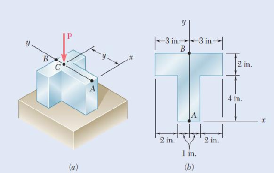
Fig. P4.118 and P4.119
Expert Solution & Answer
Want to see the full answer?
Check out a sample textbook solution
Students have asked these similar questions
3. The structure in Figure 3 is loaded by a horizontal force P = 2.4 kN at C. The roller at E is
frictionless. Find the axial force N, the shear force V and the bending moment M at a section
just above the pin B in the member ABC and illustrate their directions on a sketch of the segment
AB.
B
P
D
A
65°
65°
E
all dimensions in meters
Figure 3
4. The distributed load in Figure 4 varies linearly from 3wo per unit length at A to wo per unit
length at B and the beam is built in at A. Find expressions for the shear force V and the bending
moment M as functions of x.
3W0
Wo
A
L
Figure 4
2
B
1. The beam AB in Figure 1 is subjected to a uniformly distributed load wo = 100 N/m. Find
the axial force N, the shear force V and the bending moment M at the point D which is midway
between A and B and illustrate their directions on a sketch of the segment DB.
wo per unit length
A
D'
B
all dimensions in meters
Chapter 4 Solutions
Mechanics of Materials, 7th Edition
Ch. 4.3 - 4.1 and 4.2 Knowing that the couple shown acts in...Ch. 4.3 - 4.1 and 4.2 Knowing that the couple shown acts in...Ch. 4.3 - Using an allowable stress of 155 MPa, determine...Ch. 4.3 - Solve Prob. 4.3, assuming that the wide-flange...Ch. 4.3 - Using an allowable stress of 16 ksi, determine the...Ch. 4.3 - Knowing that the couple shown acts in a vertical...Ch. 4.3 - 4.7 and 4.8 Two W4 13 rolled sections are welded...Ch. 4.3 - 4.7 and 4.8 Two W4 13 rolled sections are welded...Ch. 4.3 - 4.9 through 4.11 Two vertical forces are applied...Ch. 4.3 - 4.9 through 4.11 Two vertical forces are applied...
Ch. 4.3 - 4.9 through 4.11 Two vertical forces are applied...Ch. 4.3 - Knowing that a beam of the cross section shown is...Ch. 4.3 - Knowing that a beam of the cross section shown is...Ch. 4.3 - Solve Prob. 4.13, assuming that the beam is bent...Ch. 4.3 - Knowing that for the extruded beam shown the...Ch. 4.3 - The beam shown is made of a nylon for which the...Ch. 4.3 - Solve Prob. 4.16, assuming that d = 40 mm.Ch. 4.3 - Knowing that for the beam shown the allowable...Ch. 4.3 - 4.19 and 4.20 Knowing that for the extruded beam...Ch. 4.3 - 4.19 and 4.20 Knowing that for the extruded beam...Ch. 4.3 - Straight rods of 6-mm diameter and 30-m length are...Ch. 4.3 - A 900-mm strip of steel is bent into a full circle...Ch. 4.3 - Straight rods of 0.30-in. diameter and 200-ft...Ch. 4.3 - A 60-Nm couple is applied to the steel bar shown,...Ch. 4.3 - (a) Using an allowable stress of 120 MPa,...Ch. 4.3 - A thick-walled pipe is bent about a horizontal...Ch. 4.3 - A couple M will be applied to a beam of...Ch. 4.3 - A portion of a square bar is removed by milling,...Ch. 4.3 - In Prob. 4.28, determine (a) the value of h for...Ch. 4.3 - For the bar and loading of Concept Application...Ch. 4.3 - Prob. 31PCh. 4.3 - It was assumed in Sec. 4.1B that the normal...Ch. 4.5 - 4.33 and 4.34 A bar having the cross section shown...Ch. 4.5 - 4.33 and 4.34 A bar having the cross section shown...Ch. 4.5 - 4.35 and 4.36 For the composite bar indicated,...Ch. 4.5 - Prob. 36PCh. 4.5 - 4.37 and 4.38 Wooden beams and steel plates are...Ch. 4.5 - 4.37 and 4.38 Wooden beams and steel plates are...Ch. 4.5 - 4.39 and 4.40 A copper strip (Ec = 105 GPa) and an...Ch. 4.5 - 4.39 and 4.40 A copper strip (Ec = 105 GPa) and an...Ch. 4.5 - 4.41 and 4.42 The 6 12-in. timber beam has been...Ch. 4.5 - 4.41 and 4.42 The 6 12-in. timber beam has been...Ch. 4.5 - 4.43 and 4.44 For the composite beam indicated,...Ch. 4.5 - Prob. 44PCh. 4.5 - Prob. 45PCh. 4.5 - Prob. 46PCh. 4.5 - A concrete slab is reinforced by 58-in.-diameter...Ch. 4.5 - Solve Prob. 4.47, assuming that the spacing of the...Ch. 4.5 - The reinforced concrete beam shown is subjected to...Ch. 4.5 - Prob. 50PCh. 4.5 - Knowing that the bending moment in the reinforced...Ch. 4.5 - A concrete beam is reinforced by three steel rods...Ch. 4.5 - The design of a reinforced concrete beam is said...Ch. 4.5 - For the concrete beam shown, the modulus of...Ch. 4.5 - 4.55 and 4.56 Five metal strips, each 0.5 1.5-in....Ch. 4.5 - 4.55 and 4.56 Five metal strips, each 0.5 1.5-in....Ch. 4.5 - The composite beam shown is formed by bonding...Ch. 4.5 - A steel pipe and an aluminum pipe are securely...Ch. 4.5 - The rectangular beam shown is made of a plastic...Ch. 4.5 - Prob. 60PCh. 4.5 - Knowing that M = 250 Nm, determine the maximum...Ch. 4.5 - Knowing that the allowable stress for the beam...Ch. 4.5 - Semicircular grooves of radius r must be milled as...Ch. 4.5 - Prob. 64PCh. 4.5 - A couple of moment M = 2 kNm is to be applied to...Ch. 4.5 - The allowable stress used in the design of a steel...Ch. 4.6 - The prismatic bar shown is made of a steel that is...Ch. 4.6 - Prob. 68PCh. 4.6 - Prob. 69PCh. 4.6 - Prob. 70PCh. 4.6 - The prismatic rod shown is made of a steel that is...Ch. 4.6 - Solve Prob. 4.71, assuming that the couples M and...Ch. 4.6 - 4.73 and 4.74 A beam of the cross section shown is...Ch. 4.6 - 4.73 and 4.74 A beam of the cross section shown is...Ch. 4.6 - 4.75 and 4.76 A beam of the cross section shown is...Ch. 4.6 - Prob. 76PCh. 4.6 - 4.77 through 4.80 For the beam indicated,...Ch. 4.6 - Prob. 78PCh. 4.6 - Prob. 79PCh. 4.6 - 4.77 through 4.80 For the beam indicated,...Ch. 4.6 - 4.81 through 4.83 Determine the plastic moment Mp...Ch. 4.6 - Prob. 82PCh. 4.6 - Prob. 83PCh. 4.6 - Determine the plastic moment Mp of a steel beam of...Ch. 4.6 - Determine the plastic moment Mp of the cross...Ch. 4.6 - Determine the plastic moment Mp of a steel beam of...Ch. 4.6 - Prob. 87PCh. 4.6 - Prob. 88PCh. 4.6 - Prob. 89PCh. 4.6 - Prob. 90PCh. 4.6 - Prob. 91PCh. 4.6 - Prob. 92PCh. 4.6 - Prob. 93PCh. 4.6 - Prob. 94PCh. 4.6 - Prob. 95PCh. 4.6 - Prob. 96PCh. 4.6 - Prob. 97PCh. 4.6 - Prob. 98PCh. 4.7 - Knowing that the magnitude of the horizontal force...Ch. 4.7 - A short wooden post supports a 6-kip axial load as...Ch. 4.7 - Two forces P can be applied separately or at the...Ch. 4.7 - A short 120 180-mm column supports the three...Ch. 4.7 - As many as three axial loads, each of magnitude P...Ch. 4.7 - Two 10-kN forces are applied to a 20 60-mm...Ch. 4.7 - Portions of a 1212-in. square bar have been bent...Ch. 4.7 - Knowing that the allowable stress in section ABD...Ch. 4.7 - A milling operation was used to remove a portion...Ch. 4.7 - A milling operation was used to remove a portion...Ch. 4.7 - The two forces shown are applied to a rigid plate...Ch. 4.7 - Prob. 110PCh. 4.7 - Prob. 111PCh. 4.7 - A short column is made by nailing four 1 4-in....Ch. 4.7 - A vertical rod is attached at point A to the cast...Ch. 4.7 - A vertical rod is attached at point A to the cast...Ch. 4.7 - Knowing that the clamp shown has been tightened...Ch. 4.7 - Prob. 116PCh. 4.7 - Three steel plates, each of 25 150-mm cross...Ch. 4.7 - A vertical force P of magnitude 20 kips is applied...Ch. 4.7 - The four bars shown have the same cross-sectional...Ch. 4.7 - Prob. 120PCh. 4.7 - An eccentric force P is applied as shown to a...Ch. 4.7 - Prob. 122PCh. 4.7 - Prob. 123PCh. 4.7 - Prob. 124PCh. 4.7 - A single vertical force P is applied to a short...Ch. 4.7 - The eccentric axial force P acts at point D, which...Ch. 4.9 - 4.127 through 4.134 The couple M is applied to a...Ch. 4.9 - 4.127 through 4.134 The couple M is applied to a...Ch. 4.9 - 4.127 through 4.134 The couple M is applied to a...Ch. 4.9 - 4.127 through 4.134 The couple M is applied to a...Ch. 4.9 - 4.127 through 4.134 The couple M is applied to a...Ch. 4.9 - 4.127 through 4.134 The couple M is applied to a...Ch. 4.9 - Prob. 133PCh. 4.9 - Prob. 134PCh. 4.9 - 4.135 through 4.140 The couple M acts in a...Ch. 4.9 - 4.135 through 4.140 The couple M acts in a...Ch. 4.9 - Prob. 137PCh. 4.9 - 4.135 through 4.140 The couple M acts in a...Ch. 4.9 - 4.135 through 44.140 The couple M acts in a...Ch. 4.9 - 4.135 through 4.140 The couple M acts in a...Ch. 4.9 - Prob. 141PCh. 4.9 - 4.141 through 4.143 The couple M acts in a...Ch. 4.9 - 4.141 through 4.143 The couple M acts in a...Ch. 4.9 - The tube shown has a uniform wall thickness of 12...Ch. 4.9 - Prob. 145PCh. 4.9 - Knowing that P = 90 kips, determine the largest...Ch. 4.9 - Knowing that a = 1.25 in., determine the largest...Ch. 4.9 - A rigid circular plate of 125-mm radius is...Ch. 4.9 - Prob. 149PCh. 4.9 - A beam having the cross section shown is subjected...Ch. 4.9 - Prob. 151PCh. 4.9 - Prob. 152PCh. 4.9 - Prob. 153PCh. 4.9 - Prob. 154PCh. 4.9 - Prob. 155PCh. 4.9 - Prob. 156PCh. 4.9 - Prob. 157PCh. 4.9 - Prob. 158PCh. 4.9 - A beam of unsymmetric cross section is subjected...Ch. 4.9 - Prob. 160PCh. 4.10 - For the curved bar shown, determine the stress at...Ch. 4.10 - For the curved bar shown, determine the stress at...Ch. 4.10 - Prob. 163PCh. 4.10 - Prob. 164PCh. 4.10 - The curved bar shown has a cross section of 40 60...Ch. 4.10 - Prob. 166PCh. 4.10 - Prob. 167PCh. 4.10 - Prob. 168PCh. 4.10 - The curved bar shown has a cross section of 30 30...Ch. 4.10 - Prob. 170PCh. 4.10 - Prob. 171PCh. 4.10 - Three plates are welded together to form the...Ch. 4.10 - 4.173 and 4.174 Knowing that the maximum allowable...Ch. 4.10 - Prob. 174PCh. 4.10 - Prob. 175PCh. 4.10 - Prob. 176PCh. 4.10 - Prob. 177PCh. 4.10 - Prob. 178PCh. 4.10 - Prob. 179PCh. 4.10 - Knowing that P = 10 kN, determine the stress at...Ch. 4.10 - Prob. 181PCh. 4.10 - Prob. 182PCh. 4.10 - Prob. 183PCh. 4.10 - Prob. 184PCh. 4.10 - Prob. 185PCh. 4.10 - Prob. 186PCh. 4.10 - Prob. 187PCh. 4.10 - Prob. 188PCh. 4.10 - Prob. 189PCh. 4.10 - Prob. 190PCh. 4.10 - For a curved bar of rectagular cross section...Ch. 4 - Two vertical forces are applied to a beam of the...Ch. 4 - Prob. 193RPCh. 4 - Prob. 194RPCh. 4 - Determine the plastic moment Mp of a steel beam of...Ch. 4 - In order to increase corrosion resistance, a...Ch. 4 - The vertical portion of the press shown consists...Ch. 4 - The four forces shown are applied to a rigid plate...Ch. 4 - Prob. 199RPCh. 4 - Prob. 200RPCh. 4 - Three 120 10-mm steel plates have been welded...Ch. 4 - A short length of a W8 31 rolled-steel shape...Ch. 4 - Two thin strips of the same material and same...
Knowledge Booster


Learn more about
Need a deep-dive on the concept behind this application? Look no further. Learn more about this topic, mechanical-engineering and related others by exploring similar questions and additional content below.Similar questions
- 5. Find the shear force V and the bending moment M for the beam of Figure 5 as functions of the distance x from A. Hence find the location and magnitude of the maximum bending moment. w(x) = wox L x L Figure 5 Barrow_forwardDry atmospheric air enters an adiabatic compressor at a 20°C, 1 atm and a mass flow rate of 0.3kg/s. The air is compressed to 1 MPa. The exhaust temperature of the air is 70 degrees hottercompared to the exhaust of an isentropic compression.Determine,a. The exhaust temperature of the air (°C)b. The volumetric flow rate (L/s) at the inlet and exhaust of the compressorc. The power required to accomplish the compression (kW)d. The isentropic efficiency of the compressore. An accounting of the exergy entering the compressor (complete Table P3.9) assuming that thedead state is the same as State 1 (dry atmospheric air)f. The exergetic efficiency of the compressorarrow_forwardA heat pump is operating between a low temperature reservoir of 270 K and a high temperaturereservoir of 340 K. The heat pump receives heat at 255 K from the low temperature reservoir andrejects heat at 355 K to the high temperature reservoir. The heating coefficient of performance ofthe heat pump is 3.2. The heat transfer rate from the low temperature reservoir is 30 kW. The deadstate temperature is 270 K. Determine,a. Power input to the heat pump (kW)b. Heat transfer rate to the high-temperature reservoir (kW)c. Exergy destruction rate associated with the low temperature heat transfer (kW)d. Exergy destruction rate of the heat pump (kW)e. Exergy destruction rate associated with the high temperature heat transfer (kW)f. Exergetic efficiency of the heat pump itselfarrow_forward
- Refrigerant 134a (Table B6, p514 of textbook) enters a tube in the evaporator of a refrigerationsystem at 132.73 kPa and a quality of 0.15 at a velocity of 0.5 m/s. The R134a exits the tube as asaturated vapor at −21°C. The tube has an inside diameter of 3.88 cm. Determine the following,a. The pressure drop of the R134a as it flows through the tube (kPa)b. The volumetric flow rate at the inlet of the tube (L/s)c. The mass flow rate of the refrigerant through the tube (g/s)d. The volumetric flow rate at the exit of the tube (L/s)e. The velocity of the refrigerant at the exit of the tube (m/s)f. The heat transfer rate to the refrigerant (kW) as it flows through the tubearrow_forwardWater enters the rigid, covered tank shown in Figure P3.2 with a volumetric flow rate of 0.32L/s. The water line has an inside diameter of 6.3 cm. The air vent on the tank has an inside diameterof 4.5 cm. The water is at a temperature of 30°C and the air in the tank is at atmospheric pressure(1 atm) and 30°C. Determine the air velocity leaving the vent at the instant shown in the figurearrow_forwardUsing method of sections, determine the force in member BC, HC, and HG. State if these members are in tension or compression. 2 kN A 5 kN 4 kN 4 kN 3 kN H B C D E 3 m F 2 m -5 m 5 m- G 5 m 5 m-arrow_forward
- Determine the normal stresses σn and σt and the shear stress τnt at this point if they act on the rotated stress element shownarrow_forwardUsing method of joints, determine the force in each member of the truss and state if the members are in tension or compression. A E 6 m D 600 N 4 m B 4 m 900 Narrow_forwardQuestion 5. The diagram below shows a mass suspended from a tie supported by two horizontal braces of equal length. The tie forms an angle "a" of 60° to the horizontal plane, the braces form an angle 0 of 50° to the vertical plane. If the mass suspended is 10 tonnes, and the braces are 10m long, find: a) the force in the tie; & b) the force in the braces Horizontal Braces, Tie Massarrow_forward
- = MMB 241 Tutorial 2.pdf 1 / 3 75% + + Tutorial z Topic: Kinematics of Particles:-. QUESTIONS 1. Use the chain-rule and find y and ŷ in terms of x, x and x if a) y=4x² b) y=3e c) y = 6 sin x 2. The particle travels from A to B. Identify the three unknowns, and write the three equations needed to solve for them. 8 m 10 m/s 30° B x 3. The particle travels from A to B. Identify the three unknowns, and write the three equations needed to solve for them. A 40 m/s 20 m B 1arrow_forward3 m³/s- 1 md 45° V 1.8 mr 2mrarrow_forward= MMB 241 Tutorial 2.pdf 3/3 75% + + 6. A particle is traveling along the parabolic path y = 0.25 x². If x = 8 m, vx=8 m/s, and ax= 4 m/s² when t = 2 s, determine the magnitude of the particle's velocity and acceleration at this instant. y = 0.25x² -x 7. Determine the speed at which the basketball at A must be thrown at the angle of 30° so that it makes it to the basket at B. 30° -x 1.5 m B 3 m -10 m- 8. The basketball passed through the hoop even though it barely cleared the hands of the player B who attempted to block it. Neglecting the size of the ball, determine the 2arrow_forward
arrow_back_ios
SEE MORE QUESTIONS
arrow_forward_ios
Recommended textbooks for you
 Elements Of ElectromagneticsMechanical EngineeringISBN:9780190698614Author:Sadiku, Matthew N. O.Publisher:Oxford University Press
 Mechanics of Materials (10th Edition)Mechanical EngineeringISBN:9780134319650Author:Russell C. HibbelerPublisher:PEARSON
 Thermodynamics: An Engineering ApproachMechanical EngineeringISBN:9781259822674Author:Yunus A. Cengel Dr., Michael A. BolesPublisher:McGraw-Hill Education
 Control Systems EngineeringMechanical EngineeringISBN:9781118170519Author:Norman S. NisePublisher:WILEY
 Mechanics of Materials (MindTap Course List)Mechanical EngineeringISBN:9781337093347Author:Barry J. Goodno, James M. GerePublisher:Cengage Learning
 Engineering Mechanics: StaticsMechanical EngineeringISBN:9781118807330Author:James L. Meriam, L. G. Kraige, J. N. BoltonPublisher:WILEY
Elements Of Electromagnetics
Mechanical Engineering
ISBN:9780190698614
Author:Sadiku, Matthew N. O.
Publisher:Oxford University Press
Mechanics of Materials (10th Edition)
Mechanical Engineering
ISBN:9780134319650
Author:Russell C. Hibbeler
Publisher:PEARSON
Thermodynamics: An Engineering Approach
Mechanical Engineering
ISBN:9781259822674
Author:Yunus A. Cengel Dr., Michael A. Boles
Publisher:McGraw-Hill Education
Control Systems Engineering
Mechanical Engineering
ISBN:9781118170519
Author:Norman S. Nise
Publisher:WILEY
Mechanics of Materials (MindTap Course List)
Mechanical Engineering
ISBN:9781337093347
Author:Barry J. Goodno, James M. Gere
Publisher:Cengage Learning
Engineering Mechanics: Statics
Mechanical Engineering
ISBN:9781118807330
Author:James L. Meriam, L. G. Kraige, J. N. Bolton
Publisher:WILEY
Relationship Between Elastic Constants and Connecting Equations; Author: Engineers Academy;https://www.youtube.com/watch?v=whW5PnM7Pug;License: Standard Youtube License