Concept explainers
(a)
Find the value of
(a)
Answer to Problem 149P
The value of
Explanation of Solution
Given information:
The radius of the circular plate is
The width of the rectangular post is
The applied force is
Calculation:
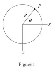
Sketch the cross section of disk as shown in Figure 1.

Refer to Figure 1.
Calculate the moment along
Substitute
Calculate the moment along
Substitute
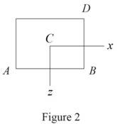
Sketch the cross section of the rectangular post as shown in Figure 2.

Refer to Figure 2.
Calculate the area
Substitute
Calculate the moment of inertia along
Substitute
Calculate the moment of inertia along
Substitute
The location of point D along
The location of point D along
Calculate the stress
Substitute
The stress
Calculate the stress at point D
Substitute
Calculate the value of
Differentiate both sides of the Equation with respect to
Substitute
Substitute
Therefore, the value of
(b)
Find the values of stress at A, B, C, and D.
(b)
Answer to Problem 149P
The stress at A is
The stress at B is
The stress at C is
The stress at D is
Explanation of Solution
Given information:
The radius of the circular plate is
The width of the rectangular post is
The applied force is
Calculation:
Refer to part (a).
The value of
The bending moment along x direction is
Substitute
The bending moment along z direction is
Substitute
Calculate the stress at A
Refer to Figure 2 in part (a).
The location of point A along
The location of point A along
Substitute
Hence, the stress at A is
Calculate the stress at B
Refer to Figure 2 in part (a).
The location of point B along
The location of point B along
Substitute
Hence, the stress at B is
Calculate the stress at C
Refer to Figure 2 in part (a).
The location of point C along
The location of point C along
Substitute
Hence, the stress at C is
Calculate the stress at D
Refer to Figure 2 in part (a).
The location of point D along
The location of point D along
Substitute
Therefore, the stress at D is
Want to see more full solutions like this?
Chapter 4 Solutions
Mechanics of Materials, 7th Edition
- L + ined sove in peaper X-P 96852 Example 5.5 The turbine rotor of a ship has a mass of 30 tons, a radius of gyration of 600 mm and rotates at 2400 rpm in a clockwise direction when viewed from aft. The ship pitches through a total angle of 15%, 7.5° above and 7.5° below the horizontal, the motion being simple harmonic and having a period of 12 sec. Determine the maximum gyroscopic couple on the holding down bolts of the turbine and the direction of yaw as the bow rises. -20125 750 x2.01arrow_forwardExample 5.5 The turbine rotor of a ship has a mass of 30 tons, a radius of gyration of 600 mm and rotates at 2400 rpm in a clockwise direction when viewed from aft. The ship pitches through a total angle of 15%, 7.5° above and 7.5° below the horizontal, the motion being simple harmonic and having a period of 12 sec. Determine the maximum gyroscopic couple on the holding down bolts of the turbine and the direction of yaw as the bow rises.arrow_forwardPlease explain each step, writing euler rates etcarrow_forward
- 5. (计算题) Calculate the DOF of following mechanisms. If there are compound hinge, passive DOF or Redundant Constraint, please point them out. 品 ⑤A (a) 凸轮拨杆机构arrow_forward6.(计算题) Calculate the DOF of following mechanisms. If there are compound hinge, passive DOF or Redundant Constraint, please point them out. E D A B C Farrow_forwardA hot surface at 150°C is to be cooled by attaching 3-cm-long, 0.25-cm-diameter aluminum pin fins (k = 237 W/m-K) to it, with a center- to-center distance of 0.6 cm. The temperature of the surrounding medium is 30°C, and the heat transfer coefficient on the surfaces is 35 W/m²K. Determine the rate of heat transfer from the surface for a 1-m × 1-m section of the plate. Also determine the overall effectiveness of the fins. 0.6 cm 0.25 cm The total rate of heat transfer is kW. The fin effectiveness isarrow_forward
- Consider a stainless steel spoon (k = 8.7 Btu/h·ft·°F) partially immersed in boiling water at 200°F in a kitchen at 75°F. The handle of the spoon has a cross section of 0.08 in × 0.5 in and extends 7 in in the air from the free surface of the water. The heat transfer coefficient at the exposed surfaces of the spoon handle is 3 Btu/h·ft2·°F. NOTE: This is a multi-part question. Once an answer is submitted, you will be unable to return to this part. A spoon is placed inside the container, such that the distance of the water level from the top end of the handle of the spoon is 7 meters. T sub air is indicated in the region outside the container. Identify the assumptions required to solve the problem. Check All That Apply One-dimensional heat transfer analysis is used to solve the problem. One-dimensional heat transfer analysis is used to solve the problem. Bi-dimensional heat transfer analysis is used to solve the problem. Bi-dimensional heat transfer analysis is…arrow_forwardA turbine blade made of a metal alloy (k=17 W/m-K) has a length of 5.3 cm, a perimeter of 11 cm, and a cross-sectional area of 5.13 cm². The turbine blade is exposed to hot gas from the combustion chamber at 1133°C with a convection heat transfer coefficient of 538 W/m²K. The base of the turbine blade maintains a constant temperature of 450°C and the tip is adiabatic. NOTE: This is a multi-part question. Once an answer is submitted, you will be unable to return to this part. Hot gas h=538 W/m²K -Turbine blade k = 17 W/m-K p=11 cm, L=5.3 cm A = 5.13 cm² -T=450°C Determine the heat transfer rate to the turbine blade. W. The heat transfer rate isarrow_forwardConsider a very long, slender rod. One end of the rod is attached to a base surface maintained at Tb, while the surface of the rod is exposed to an air temperature of 400°C. Thermocouples imbedded in the rod at locations 25 mm and 120 mm from the base surface register temperatures of 325°C and 375°C, respectively. NOTE: This is a multi-part question. Once an answer is submitted, you will be unable to return to this part. . x1 32 x Calculate the rod base temperature (°C). The rod base temperature is °C. Air T∞arrow_forward
 Elements Of ElectromagneticsMechanical EngineeringISBN:9780190698614Author:Sadiku, Matthew N. O.Publisher:Oxford University Press
 Mechanics of Materials (10th Edition)Mechanical EngineeringISBN:9780134319650Author:Russell C. HibbelerPublisher:PEARSON
 Thermodynamics: An Engineering ApproachMechanical EngineeringISBN:9781259822674Author:Yunus A. Cengel Dr., Michael A. BolesPublisher:McGraw-Hill Education
 Control Systems EngineeringMechanical EngineeringISBN:9781118170519Author:Norman S. NisePublisher:WILEY
 Mechanics of Materials (MindTap Course List)Mechanical EngineeringISBN:9781337093347Author:Barry J. Goodno, James M. GerePublisher:Cengage Learning
 Engineering Mechanics: StaticsMechanical EngineeringISBN:9781118807330Author:James L. Meriam, L. G. Kraige, J. N. BoltonPublisher:WILEY


