
Suppose we have a capacitance C discharging through a resistance R. Define and give an expression for the time constant. To attain a long time constant, do we need large or small values for R? For C?
The expression for the time constant of the discharging RC circuit and the magnitude of values of R and C for the condition of a large time constant.
Answer to Problem 4.1P
The expression for the time constant for the discharging RC circuit is given as
The value of the values of R and C must be high for a large time constant.
Explanation of Solution
Given information:
Initially, the capacitor is fully charged, the charge on the plates of the capacitor at
The capacitance of the capacitor is C, the resistance of the resistor is R and the time constant of the circuit is
Calculation:
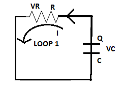
The circuit diagram of the discharging RC circuit is shown below. The capacitor is initially fully charged. Since it is a discharging circuit, the charges on the plate of the capacitor are Q after a time
Applying K.V.L in loop 1
Let the charge on the capacitor at any instant is
Solving the differential equation (2) using the variable separable method,
Where
Hence, the time constant is proportional to the values of resistance and capacitance in the circuit.
To attain a large time constant large value of R is needed as R is directly proportional to the time constant. Also, a large value of C is needed for a large time constant.
Want to see more full solutions like this?
Chapter 4 Solutions
Electrical Engineering: Principles & Applications (7th Edition)
Additional Engineering Textbook Solutions
Starting Out with Java: From Control Structures through Data Structures (4th Edition) (What's New in Computer Science)
Starting Out with C++ from Control Structures to Objects (9th Edition)
INTERNATIONAL EDITION---Engineering Mechanics: Statics, 14th edition (SI unit)
Java How to Program, Early Objects (11th Edition) (Deitel: How to Program)
Mechanics of Materials (10th Edition)
Starting Out with Programming Logic and Design (5th Edition) (What's New in Computer Science)

- 2. Consider following feedback system. r(t) e(t) y(t) K G(s) 1 where G(S) = s²+as+b In above, K, a and b are constants. Select the values of K, a and b in a way so that (i) (ii) (iii) the closed loop system is stable, steady-state error of the closed-loop system for step input is 0.2, the closed-loop response has 20% overshoot and 2 seconds as settling time.arrow_forward4. Answer the following questions. Take help from ChatGPT to answer these questions (if you need). But write the answers briefly using your own words with no more than two sentences, and make sure you check whether ChatGPT is giving you the appropriate answers in the context of class. a) What is the advantage of the PI controller over the proportional controller? b) What is the advantage of the PD controller over a proportional controller? c) In the presence of noise, what problem do we face implementing the derivate part of the PID (or PD) controller? To address this, what do we usually use? d) What are the forms of lead compensator and lag compensator? How do these two types of compensators differ?arrow_forward3. Consider the following closed-loop system as shown in the figure. 16 Ge(s) s(s + 4) Suppose Ge(s) is a PID controller with Kp = 1, KD = 2 and K₁ = 3. a) Find the controller transfer function G₁(s). b) Find the open-loop transfer function. c) Find the closed-loop transfer function.arrow_forward
- Exercise 3-12: Find the Thévenin equivalent of the circuit to the left of terminals (a, b) in Fig. E3.12, and then determine the current I. 502 5 Ω 0.6 Ω a 3Ω ΣΙΩ b 20 V 1 + 2027 15A Figure E3.12arrow_forwardsolve and show workarrow_forwardDon't use ai to answer I will report you answerarrow_forward
- values. 4. Discussion: DEPA الأمهريائية RING Compare between theoretic bination effect of Kp and KI at first order and second order systems regarding steady-state errors and transient responses with the practical. In Experiment PI Controllerarrow_forwardⓇ 1. Discuss the relationship between DMA-out and A-out signals. 2. Explain the results of steps 3 and 4 in Experiment 16-2. Unit 16 CVSD System Table 16-2 CVSD demodulator (CLK out - 90KHz) A-in Input Signal DMD-out Waveform & Frequency DMA-out Waveform & Frequency TKHz 1Vpp Sinewave 3KHz 1Vpp Sinewave 200Hz 1Vpp Sinewavearrow_forward3. Describe the function of the lowpass filter (LPF) used in CVSD system.arrow_forward
- Don't use ai to answer I will report you answerarrow_forwardRL +Vcc a VCE 2. a) For the direct coupled class A amplifier shown, derive the expression for efficiency in terms of maximum and minimum values of currents and voltages. b) Determine the maximum efficiency of this circuit. c) Derive the expression for maximum power dissipation. www 9 www RB in VBEarrow_forwardDon't use ai to answer I will report you answerarrow_forward
 Introductory Circuit Analysis (13th Edition)Electrical EngineeringISBN:9780133923605Author:Robert L. BoylestadPublisher:PEARSON
 Delmar's Standard Textbook Of ElectricityElectrical EngineeringISBN:9781337900348Author:Stephen L. HermanPublisher:Cengage Learning
 Programmable Logic ControllersElectrical EngineeringISBN:9780073373843Author:Frank D. PetruzellaPublisher:McGraw-Hill Education
 Fundamentals of Electric CircuitsElectrical EngineeringISBN:9780078028229Author:Charles K Alexander, Matthew SadikuPublisher:McGraw-Hill Education
 Electric Circuits. (11th Edition)Electrical EngineeringISBN:9780134746968Author:James W. Nilsson, Susan RiedelPublisher:PEARSON
 Engineering ElectromagneticsElectrical EngineeringISBN:9780078028151Author:Hayt, William H. (william Hart), Jr, BUCK, John A.Publisher:Mcgraw-hill Education,