
Electronics Fundamentals: Circuits, Devices & Applications
8th Edition
ISBN: 9780135072950
Author: Thomas L. Floyd, David Buchla
Publisher: Prentice Hall
expand_more
expand_more
format_list_bulleted
Concept explainers
Videos
Textbook Question
Chapter 4, Problem 37P
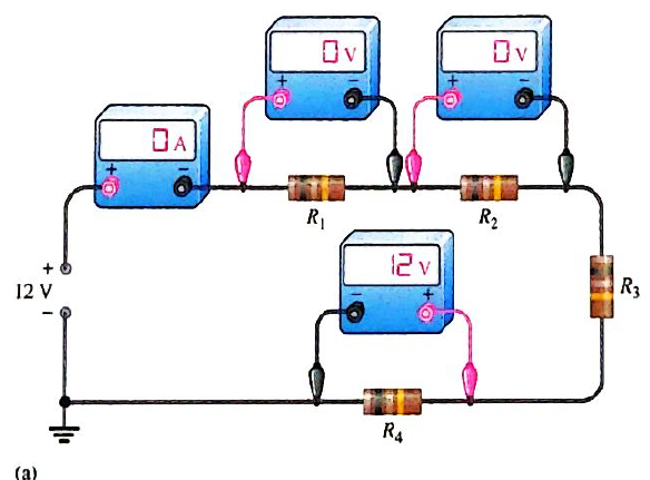
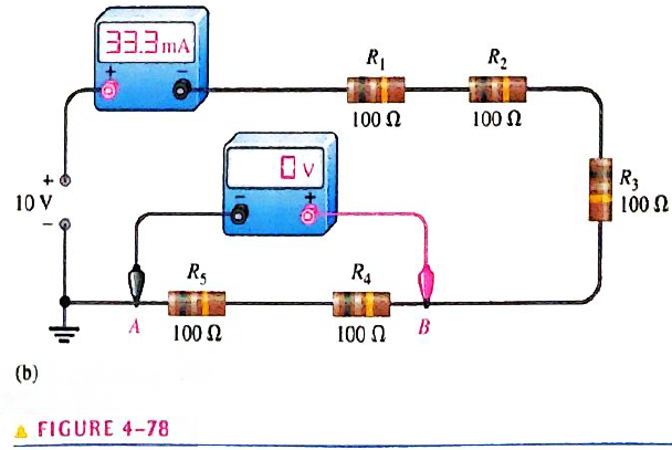
By observing the meters in Figure 4-78, determine the types of failures in the circuits and which components have failed.
Expert Solution & Answer
Want to see the full answer?
Check out a sample textbook solution
Students have asked these similar questions
Design a full-wave rectifier power supply using a 9.52:1 transformer. Assume that the outlet is120 V rms @ 60 Hz. Further assume that the diode turn-on voltage V D(on) is 0.7 V. Pick the valueof CL such that vo has a maximum ripple of 1 V p-p . Solve for the average value of vo = Vo (notethat this may be greater than 12 V) and iD(ave) = ID.
Light-emitting diodes (LEDs) are diodes made with III-V compound semiconductor materials such as aluminum gallium arsenide (AlGaAs), aluminum indium gallium phosphide (AlInGaP) or indium gallium nitride (InGaN), instead of silicon. The LEDs emit light when the device is operated under forward bias. LEDs of different colors have different turn-on voltages VD(on). For example:
VD(on) :
Red: ~ 1.6 V
Yellow: ~ 1.7 V
Green: ~ 1.8 V
Blue: ~ 2.8 V
White: ~ 3.8 V
(a) Model these five LEDs with a simplified piecewise linear model
(b) A rule of thumb is that it takes about 1 mA of current to “light” an LED while ~ 10 mA is needed for it to appear bright. Use the piecewise linear model for the LEDs, for the over-voltage indicator circuit to the right, find the values of Vin which will cause D1 or D2 to light (i.e. when ID1 or ID2 exceeds 1 mA).
Consider a fixed and updated instrumentation amplifier (where two resistors are lumped into one
resistor), analyze the circuit if a common voltage source (VICM) is connected to two inputs.
A₁
R₂
+
R₁
R₂,
RA
www
www
R₁
R₁
www
A3
X
R₁
R₂
www
www
R₁₂
+
Vo
RA
A2
V2 O-
+
R₂
12
R₁
Chapter 4 Solutions
Electronics Fundamentals: Circuits, Devices & Applications
Ch. 4 - A series circuit can have more than one path for...Ch. 4 - The total resistance of a series circuit can be...Ch. 4 - If two series resistors are different sizes, the...Ch. 4 - If two series resistors are different sizes, the...Ch. 4 - If three equal resistors are used in a voltage...Ch. 4 - Prob. 6TFQCh. 4 - Kirchhoff’s voltage law is valid only if a loop...Ch. 4 - Prob. 8TFQCh. 4 - Prob. 9TFQCh. 4 - If point A in a cricuit has a voltage of +10V and...
Ch. 4 - Prob. 1STCh. 4 - To measure the current out of the third resistor...Ch. 4 - Prob. 3STCh. 4 - When one of four series resistors is removed from...Ch. 4 - A series circuit consists of three resistors with...Ch. 4 - A 9 V battery is connected across a series...Ch. 4 - While putting four 1.5 V batteries in a...Ch. 4 - Prob. 8STCh. 4 - Prob. 9STCh. 4 - A series circuit consists of a 4.7k a 5.6k and a...Ch. 4 - Prob. 11STCh. 4 - Prob. 12STCh. 4 - When you connect an ammeter in a series resistive...Ch. 4 - While checking out a series resistive circuit, you...Ch. 4 - Determine the cause for each set of symptoms....Ch. 4 - Prob. 2TSCCh. 4 - Prob. 3TSCCh. 4 - Symptom: The ammeter reading is zero, voltmeter 1...Ch. 4 - Symptom: The ammeter reading is 0.645mA, the...Ch. 4 - Connect each set of resistors in Figure 4-64 in...Ch. 4 - Determine which resistors in Figure 4-65 are in...Ch. 4 - Determine the resistance between pins 1 and 8 in...Ch. 4 - Determine the resistance between pins 2 and 3 in...Ch. 4 - An 82 resistor and a 56 resistor are connected in...Ch. 4 - Find the total resistance of each group of series...Ch. 4 - Determine RT for each circuit in Figure 4-67. Show...Ch. 4 - What is the total resistance of twelve 5.6k...Ch. 4 - Six 47 resistors, eight 100 resistors, and two 22...Ch. 4 - The total resistance in Figure 4-68 is 20k. What...Ch. 4 - Determine the resistance between each of the...Ch. 4 - If all the resistors in Figure 4-65 are connected...Ch. 4 - What is the current through each of four resistors...Ch. 4 - The current from the source in Figure 4-69 is 5...Ch. 4 - What is the current in each circuit of Figure...Ch. 4 - 16. Determine the voltage across each resistor in...Ch. 4 - Three 470 resistors are in series with a 48 V...Ch. 4 - Four equal-value resitors are in series with a 5 V...Ch. 4 - Show how to connect four 6 V batteries to achieve...Ch. 4 - What happens if one of the batteries in Problem 19...Ch. 4 - The following voltage drops are measured across...Ch. 4 - Five resistors are in series with a 20 V source....Ch. 4 - Determine the unspecified voltage drop(s) in each...Ch. 4 - The total resistance of a series circuit is 500....Ch. 4 - Find the voltage between A and B in each voltage...Ch. 4 - Determine the voltage with respect to ground for...Ch. 4 - Determine the minimum and maximum output voltage...Ch. 4 - What is the voltage across each resistor in Figure...Ch. 4 - What is the voltage across each resistor on the...Ch. 4 - Five series resistors each dissipate 50 mW of...Ch. 4 - Find the total power in Figure 4-75.Ch. 4 - Prob. 32PCh. 4 - In Figure 4-77, how would you determine the...Ch. 4 - Determine the voltage at each point with respect...Ch. 4 - In Figure 4-77, what is VAC?Ch. 4 - In Figure 4-77, what is VCA?Ch. 4 - By observing the meters in Figure 4-78, determine...Ch. 4 - Is the multimeter reading in Figure 4-79 correct?...Ch. 4 - Determine the unknown resistance (R3) in the...Ch. 4 - You have the following resistor values available...Ch. 4 - Determine the voltage at each point in Figure 4-81...Ch. 4 - Find all the unknown quantities (shown in red) in...Ch. 4 - There are 250 mA in a series circuit with a total...Ch. 4 - Four 12W resistors are in series:...Ch. 4 - A certain series circuit is made up of a 18W...Ch. 4 - Using 1.5 V batteries, a switch, and three lamps,...Ch. 4 - Prob. 47PCh. 4 - Using the standard resistor values given in...Ch. 4 - On the double-sided PC board in Figure 4-83,...Ch. 4 - What is the total resistance from A to B for each...Ch. 4 - Determine the current measured by the meter in...Ch. 4 - Prob. 52PCh. 4 - Determine the voltage across each resistor in...Ch. 4 - Table 4-1 shows the results of resistance...Ch. 4 - You measure 15k between pins 5 and 6 on the PC...Ch. 4 - In checking out the PC board in Figure 4-83, you...Ch. 4 - The three groups of series resistors on the PC...Ch. 4 - Open file P04-58: Files are found at...Ch. 4 - Open file P04-59. Determine if there is a fault...Ch. 4 - Open file P04-60. Determine if there is a fault...Ch. 4 - Open file P04-61. Determine if there is a fault...Ch. 4 - Open file P04-62. Determine if there is a fault...Ch. 4 - www.prenhall.com/floyd. 63. Open file P04-63....
Knowledge Booster


Learn more about
Need a deep-dive on the concept behind this application? Look no further. Learn more about this topic, electrical-engineering and related others by exploring similar questions and additional content below.Similar questions
- Show that the input impedance of a lossy transmission line of length L connected to a load impedance of Z is given by Z₁Cosh(yL) + ZoSinh(yL) Zin = Zo ZoCosh(YL) + Z₁Sihh(YL) ex Where Cosh(x) = and Sinh(x) = are the hyperbolic cosine and sine, respectively. 2 2arrow_forwardA sinusoidal source of V = 10 and Z = 50 - j40 is connected to a 60 lossless transmission line of length 100 m with ẞ = 0.25. What is the Thevenin's equivalent of this system seen looking into the load end of the transmission line?arrow_forward2. On a distortionless transmission line, the voltage wave is given by v(L,t) = 110e0.005L Cos(10³t + 2L) +55e-0.005L Cos(108t-2L) where L is the length of the transmission line as measured from the load. If Z = 30002, find a,ẞ, vp, and Zo.arrow_forward
- A 50 transmission line is to be connected to a 72 load through a 1/4 quarter wave matching transformer. (a) What must be the characteristic impedance of the transmission line that is used to form the quarter wave transformer? (b) If the frequency of operation is 7 MHz and the phase velocity through the quarter wave section is 2c/3, what is the length of the quarter wave section? You may assume the transmission line forming the quarter wave section is lossless.arrow_forwardWhat is the SWR on a transmission line if the forward power arriving at the load is 5W but only 4.6W is dissipated by the load?arrow_forwardPlease do not send the AI solution as it is full of errors. Solve the question yourself, please. Q- If you have a unipolar winding stepper motor, draw the driver and the control circuit. In subject (A stepper motor driver circuit and direction control using Arduino microcontroller)arrow_forward
- 1- Draw the complete circuit diagram that illustrates the experiment concept as in figure 5 by showing the pins number. Show the following in your plot (Arduino board, steppermotor coils and the driver circuit). Note: The drawing should be on paper and not with artificial intelligence, please.arrow_forwardIn the circuit shown, find the following: 1) The current Ix. 2) The average power dissipated in the capacitor. 3) The total average power dissipated in the two resistors. 4) The average power of the independent voltage source and specify whether it is supplied or absorbed. 5) The total impedance seen from the terminals of the independent voltage source (Z=V/I). 20 -201 12/00V(+ 21 www 202arrow_forward2- If you have a unipolar winding stepper motor, draw the driver and the control circuit. Note: The drawing is on paper.arrow_forward
- Given the following reaction system, where Xo is the input, i.e u(t) = k₁ × Xo: $Xo -> x1; k1*Xo x2; k2*x1 x1 2 x2 ->%; k3*x2^2 x2 ->; k4*x2 Xo 1; k1 = 0.4 k2 4.5; k3 = 0.75 k4= 0.2 a) Build the model in Tellurium and run a simulation. Compute the Jacobian at steady state using the method getFull Jacobian(). Make sure you are at steady state! b) Write out the values for n and p c) Write out the differential equations. d) Write out the state space representation in terms of the rate constants etc. e) Compute the values in the Jacobian matrix from d) by substituting the values of the rate constants etc and any data you need from the simulation. f) Confirm that the Jacobian you get in e) is the same as the one computed from the simulation in a). g) Is the system stable or not? If you find an eigenvalue of zero, that means the system is marginally stable. You can get the eigenvalues using the tellurium method r.getFullEigenvalues()arrow_forwardSolve by Pen and Paper not using chatgpt or AIarrow_forwardYou just got a job at Shin-Etsu Chemical growing Si crystals with different dopants. Howmuch Ga needs to be added to 800 kg of Si melt to achieve a 5-10 Ω.cm (measured at midheight) Si CZ crystal with the following characteristics: height: 7 ft, width: 12 inchesdiameter. Assume, angular rotation 10 RPM, melt viscosity 0.1 poise, pull velocity 2mm/min.a. Generate a plot of the doping distribution throughout the length of the crystal (CGa vs. fs ).b. If a second crystal were to be pulled out of the melt without replenishment of silicon nordopant what would be the average resistivity of this crystal (or resistivity at mid height)arrow_forward
arrow_back_ios
SEE MORE QUESTIONS
arrow_forward_ios
Recommended textbooks for you
 Delmar's Standard Textbook Of ElectricityElectrical EngineeringISBN:9781337900348Author:Stephen L. HermanPublisher:Cengage Learning
 Electricity for Refrigeration, Heating, and Air C...Mechanical EngineeringISBN:9781337399128Author:Russell E. SmithPublisher:Cengage Learning
 EBK ELECTRICAL WIRING RESIDENTIALElectrical EngineeringISBN:9781337516549Author:SimmonsPublisher:CENGAGE LEARNING - CONSIGNMENT
Delmar's Standard Textbook Of Electricity
Electrical Engineering
ISBN:9781337900348
Author:Stephen L. Herman
Publisher:Cengage Learning
Electricity for Refrigeration, Heating, and Air C...
Mechanical Engineering
ISBN:9781337399128
Author:Russell E. Smith
Publisher:Cengage Learning
EBK ELECTRICAL WIRING RESIDENTIAL
Electrical Engineering
ISBN:9781337516549
Author:Simmons
Publisher:CENGAGE LEARNING - CONSIGNMENT
What is an electric furnace and how does it work?; Author: Fire & Ice Heating and Air Conditioning Inc;https://www.youtube.com/watch?v=wjAWecPGi0M;License: Standard Youtube License