
Electronics Fundamentals: Circuits, Devices & Applications
8th Edition
ISBN: 9780135072950
Author: Thomas L. Floyd, David Buchla
Publisher: Prentice Hall
expand_more
expand_more
format_list_bulleted
Concept explainers
Videos
Textbook Question
Chapter 4, Problem 33P
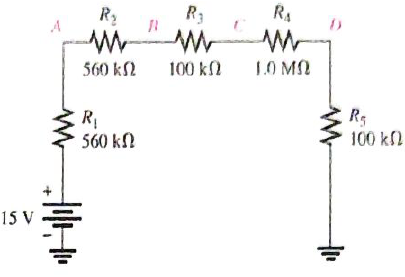
In Figure 4-77, how would you determine the voltage across
Expert Solution & Answer
Want to see the full answer?
Check out a sample textbook solution
Students have asked these similar questions
a) A silicon wafer is uniformly doped p-type with NA=10¹³/cm³. At T=0K, what are the equilibrium
hole and electron concentrations?
1016
1015
Ge
101
Si
1013
1012
GaAs
10"
(( uວ) uot¤ງແລ້ວuo ວາ.ຂ ວາsuuuT
0101
601
801
107
10%
Determine the equilibrium electron and hole concentrations inside a uniformly doped sample of Si
under the following conditions. (n; =1010/cm³ at 300K)
a) T 300 K, NA << ND, ND = 1015/cm³
b) T 300 K, NA = 9X10¹⁵/cm³, ND = 1016/cm³
c) T = 450 K, NA = 0, ND = 1014/cm³
d) T = 650 K, NA = 0, ND = 1014/cm³
10°
200
300
400
500
600
700
T(K)
b) A semiconductor is doped with an impurity concentration N such that N >> n; and all the
impurities are ionized. Also, n = N and p = n2/N. Is the impurity a donor or an acceptor? Explain.
Chapter 4 Solutions
Electronics Fundamentals: Circuits, Devices & Applications
Ch. 4 - A series circuit can have more than one path for...Ch. 4 - The total resistance of a series circuit can be...Ch. 4 - If two series resistors are different sizes, the...Ch. 4 - If two series resistors are different sizes, the...Ch. 4 - If three equal resistors are used in a voltage...Ch. 4 - Prob. 6TFQCh. 4 - Kirchhoff’s voltage law is valid only if a loop...Ch. 4 - Prob. 8TFQCh. 4 - Prob. 9TFQCh. 4 - If point A in a cricuit has a voltage of +10V and...
Ch. 4 - Prob. 1STCh. 4 - To measure the current out of the third resistor...Ch. 4 - Prob. 3STCh. 4 - When one of four series resistors is removed from...Ch. 4 - A series circuit consists of three resistors with...Ch. 4 - A 9 V battery is connected across a series...Ch. 4 - While putting four 1.5 V batteries in a...Ch. 4 - Prob. 8STCh. 4 - Prob. 9STCh. 4 - A series circuit consists of a 4.7k a 5.6k and a...Ch. 4 - Prob. 11STCh. 4 - Prob. 12STCh. 4 - When you connect an ammeter in a series resistive...Ch. 4 - While checking out a series resistive circuit, you...Ch. 4 - Determine the cause for each set of symptoms....Ch. 4 - Prob. 2TSCCh. 4 - Prob. 3TSCCh. 4 - Symptom: The ammeter reading is zero, voltmeter 1...Ch. 4 - Symptom: The ammeter reading is 0.645mA, the...Ch. 4 - Connect each set of resistors in Figure 4-64 in...Ch. 4 - Determine which resistors in Figure 4-65 are in...Ch. 4 - Determine the resistance between pins 1 and 8 in...Ch. 4 - Determine the resistance between pins 2 and 3 in...Ch. 4 - An 82 resistor and a 56 resistor are connected in...Ch. 4 - Find the total resistance of each group of series...Ch. 4 - Determine RT for each circuit in Figure 4-67. Show...Ch. 4 - What is the total resistance of twelve 5.6k...Ch. 4 - Six 47 resistors, eight 100 resistors, and two 22...Ch. 4 - The total resistance in Figure 4-68 is 20k. What...Ch. 4 - Determine the resistance between each of the...Ch. 4 - If all the resistors in Figure 4-65 are connected...Ch. 4 - What is the current through each of four resistors...Ch. 4 - The current from the source in Figure 4-69 is 5...Ch. 4 - What is the current in each circuit of Figure...Ch. 4 - 16. Determine the voltage across each resistor in...Ch. 4 - Three 470 resistors are in series with a 48 V...Ch. 4 - Four equal-value resitors are in series with a 5 V...Ch. 4 - Show how to connect four 6 V batteries to achieve...Ch. 4 - What happens if one of the batteries in Problem 19...Ch. 4 - The following voltage drops are measured across...Ch. 4 - Five resistors are in series with a 20 V source....Ch. 4 - Determine the unspecified voltage drop(s) in each...Ch. 4 - The total resistance of a series circuit is 500....Ch. 4 - Find the voltage between A and B in each voltage...Ch. 4 - Determine the voltage with respect to ground for...Ch. 4 - Determine the minimum and maximum output voltage...Ch. 4 - What is the voltage across each resistor in Figure...Ch. 4 - What is the voltage across each resistor on the...Ch. 4 - Five series resistors each dissipate 50 mW of...Ch. 4 - Find the total power in Figure 4-75.Ch. 4 - Prob. 32PCh. 4 - In Figure 4-77, how would you determine the...Ch. 4 - Determine the voltage at each point with respect...Ch. 4 - In Figure 4-77, what is VAC?Ch. 4 - In Figure 4-77, what is VCA?Ch. 4 - By observing the meters in Figure 4-78, determine...Ch. 4 - Is the multimeter reading in Figure 4-79 correct?...Ch. 4 - Determine the unknown resistance (R3) in the...Ch. 4 - You have the following resistor values available...Ch. 4 - Determine the voltage at each point in Figure 4-81...Ch. 4 - Find all the unknown quantities (shown in red) in...Ch. 4 - There are 250 mA in a series circuit with a total...Ch. 4 - Four 12W resistors are in series:...Ch. 4 - A certain series circuit is made up of a 18W...Ch. 4 - Using 1.5 V batteries, a switch, and three lamps,...Ch. 4 - Prob. 47PCh. 4 - Using the standard resistor values given in...Ch. 4 - On the double-sided PC board in Figure 4-83,...Ch. 4 - What is the total resistance from A to B for each...Ch. 4 - Determine the current measured by the meter in...Ch. 4 - Prob. 52PCh. 4 - Determine the voltage across each resistor in...Ch. 4 - Table 4-1 shows the results of resistance...Ch. 4 - You measure 15k between pins 5 and 6 on the PC...Ch. 4 - In checking out the PC board in Figure 4-83, you...Ch. 4 - The three groups of series resistors on the PC...Ch. 4 - Open file P04-58: Files are found at...Ch. 4 - Open file P04-59. Determine if there is a fault...Ch. 4 - Open file P04-60. Determine if there is a fault...Ch. 4 - Open file P04-61. Determine if there is a fault...Ch. 4 - Open file P04-62. Determine if there is a fault...Ch. 4 - www.prenhall.com/floyd. 63. Open file P04-63....
Knowledge Booster


Learn more about
Need a deep-dive on the concept behind this application? Look no further. Learn more about this topic, electrical-engineering and related others by exploring similar questions and additional content below.Similar questions
- d) For a silicon sample maintained at T=300K, the Fermi level is located 0.259 eV above the intrinsic Fermi level. What are the hole and electron concentrations?arrow_forwarde) In a nondegenerate germanium sample maintained under equilibrium conditions near room temperature, it is known that n=10¹³/cm³, n = 2p, and NA 0. Determine n and ND.arrow_forwardSolve fo the voltage across the 1kohm resistor using superposition for the three following cases: only V1 present, only V2 present, and both V1 and V2 present.arrow_forward
- Semiconductor A has a band gap of 1eV, while semiconductor B has a band gap of 2eV. What is the ration of the intrinsic carrier concentrations in the two materials (n₁A/NB) at 300 K. Assume any differences in the carrier effective masses may be neglected.arrow_forwardc) The electron concentration in a piece of Si maintained at 300K under equilibrium conditions is 105/cm³. What is the hole concentration?arrow_forward5. Represent the following system in state-space form. Write A, B, C and D clearly in your answer. d³y d²y dt3 - +5y=2u dt²arrow_forward
- 3. Find the transfer function H(s) and frequency response H (w) of the following system whose differential equation is given by d¹y d³y +3. dy +5 dt4 dt3 dt - d²u du 4y = - 5 dt² dtarrow_forward1. Consider a plant that you want to control. The input u(t) and output y(t) of the plant are related by y(t) = 7 u(t) + w(t) where w(t) is an additive disturbance at the output which is bounded by -0.5 w(t) ≤0.5 for all time t. You want to build a controller so that the output follows a constant reference signal r(t) = where -15 ≤≤ 15. You will consider both open-loop and closed-loop for this problem. a) Sketch the block diagram of the plant. b) Please build an open-loop controller that sets the output to 7, assuming the disturbance is ignored. Please show your controller both as an equation and a block diagram. c) Say that you use the open-loop controller in part b, but now the disturbance w(t) is present. What is the maximum possible magnitude of error in the output for the reference signal? Suppose you have designed a feedback control for the plant where the controller has the form u(t) = K(r(t) − y(t)). Here K is the gain constant of the controller that you will design. d) Please…arrow_forward2. Suppose the Laplace transform of a causal signal x(t) is given by s² +2 X(s) = S³ + 1 Using the lookup tables for standard Laplace transforms and the Laplace transform properties, find the Laplace transforms of the following signals. You do not need to simplify the expressions. a) x₁(t) = e² x(t) + 38(t − 1) − (t − 2)² u(t − 2) b) x2(t) = x(2t - 1) + et u(t − 2)arrow_forward
- Please explain in detail the steps to solve this. Thank youarrow_forward6. Answer the following questions. Take help from ChatGPT to answer these questions (if you need). But write the answers briefly using your own words with no more than two sentences and make sure you check whether ChatGPT is giving you the appropriate answers in our context. a) What is the difference between a regulator and a servo system? Which is harder to build? b) What are the advantages and drawbacks of manual control systems over automatic ones? c) Does transfer exist for the non-linear systems? d) Explain the convolution property of the Laplace transform. e) What are the advantages of using state-space representation?arrow_forward4. Find the differential equation of the following system whose transfer function is given by S+3 H(s) = s3 +3s+2arrow_forward
arrow_back_ios
SEE MORE QUESTIONS
arrow_forward_ios
Recommended textbooks for you
 Electricity for Refrigeration, Heating, and Air C...Mechanical EngineeringISBN:9781337399128Author:Russell E. SmithPublisher:Cengage Learning
Electricity for Refrigeration, Heating, and Air C...
Mechanical Engineering
ISBN:9781337399128
Author:Russell E. Smith
Publisher:Cengage Learning
What is an electric furnace and how does it work?; Author: Fire & Ice Heating and Air Conditioning Inc;https://www.youtube.com/watch?v=wjAWecPGi0M;License: Standard Youtube License