
Electronics Fundamentals: Circuits, Devices & Applications
8th Edition
ISBN: 9780135072950
Author: Thomas L. Floyd, David Buchla
Publisher: Prentice Hall
expand_more
expand_more
format_list_bulleted
Concept explainers
Videos
Textbook Question
Chapter 4, Problem 27P
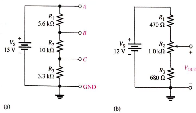
Determine the minimum and maximum output voltage from the voltage divider in Figure 4-73(b).
Expert Solution & Answer
Want to see the full answer?
Check out a sample textbook solution
Students have asked these similar questions
Consider the Difference equation of a causal Linear time-invariant (LTI) system given
by: (y(n) - 1.5y(n - 1) + 0.5y(n = 2) = x(n)
a) Implement the difference equation model of this system.
b) Find the system transfer function H(z).
c) For an input x(n) = 8(n), determine the output response y(n).
d) Verify the initial value theorem y(0) with part (c).
Q5B. Find the type of the controller in the following figures and use real values to find the transfer
function of three of them[ Hint Pi,Pd and Lead,lag are found so put the controller with its
corresponding compensator].
R₁
R₂
Rz
HE
C2
RA
HE
R₁
R2
RA
と
Q1// Sketch the root locus for the unity feedback system. Where
G(s)=)=
K
S3+252 +25
and find the following
a. Sketch the asymptotes
b. The exact point and gain where the locus crosses the jo-axis
c. The breakaway point on the real axis
d. The range of K within which the system is stable
e. Angles of departure and arrival.
Chapter 4 Solutions
Electronics Fundamentals: Circuits, Devices & Applications
Ch. 4 - A series circuit can have more than one path for...Ch. 4 - The total resistance of a series circuit can be...Ch. 4 - If two series resistors are different sizes, the...Ch. 4 - If two series resistors are different sizes, the...Ch. 4 - If three equal resistors are used in a voltage...Ch. 4 - Prob. 6TFQCh. 4 - Kirchhoff’s voltage law is valid only if a loop...Ch. 4 - Prob. 8TFQCh. 4 - Prob. 9TFQCh. 4 - If point A in a cricuit has a voltage of +10V and...
Ch. 4 - Prob. 1STCh. 4 - To measure the current out of the third resistor...Ch. 4 - Prob. 3STCh. 4 - When one of four series resistors is removed from...Ch. 4 - A series circuit consists of three resistors with...Ch. 4 - A 9 V battery is connected across a series...Ch. 4 - While putting four 1.5 V batteries in a...Ch. 4 - Prob. 8STCh. 4 - Prob. 9STCh. 4 - A series circuit consists of a 4.7k a 5.6k and a...Ch. 4 - Prob. 11STCh. 4 - Prob. 12STCh. 4 - When you connect an ammeter in a series resistive...Ch. 4 - While checking out a series resistive circuit, you...Ch. 4 - Determine the cause for each set of symptoms....Ch. 4 - Prob. 2TSCCh. 4 - Prob. 3TSCCh. 4 - Symptom: The ammeter reading is zero, voltmeter 1...Ch. 4 - Symptom: The ammeter reading is 0.645mA, the...Ch. 4 - Connect each set of resistors in Figure 4-64 in...Ch. 4 - Determine which resistors in Figure 4-65 are in...Ch. 4 - Determine the resistance between pins 1 and 8 in...Ch. 4 - Determine the resistance between pins 2 and 3 in...Ch. 4 - An 82 resistor and a 56 resistor are connected in...Ch. 4 - Find the total resistance of each group of series...Ch. 4 - Determine RT for each circuit in Figure 4-67. Show...Ch. 4 - What is the total resistance of twelve 5.6k...Ch. 4 - Six 47 resistors, eight 100 resistors, and two 22...Ch. 4 - The total resistance in Figure 4-68 is 20k. What...Ch. 4 - Determine the resistance between each of the...Ch. 4 - If all the resistors in Figure 4-65 are connected...Ch. 4 - What is the current through each of four resistors...Ch. 4 - The current from the source in Figure 4-69 is 5...Ch. 4 - What is the current in each circuit of Figure...Ch. 4 - 16. Determine the voltage across each resistor in...Ch. 4 - Three 470 resistors are in series with a 48 V...Ch. 4 - Four equal-value resitors are in series with a 5 V...Ch. 4 - Show how to connect four 6 V batteries to achieve...Ch. 4 - What happens if one of the batteries in Problem 19...Ch. 4 - The following voltage drops are measured across...Ch. 4 - Five resistors are in series with a 20 V source....Ch. 4 - Determine the unspecified voltage drop(s) in each...Ch. 4 - The total resistance of a series circuit is 500....Ch. 4 - Find the voltage between A and B in each voltage...Ch. 4 - Determine the voltage with respect to ground for...Ch. 4 - Determine the minimum and maximum output voltage...Ch. 4 - What is the voltage across each resistor in Figure...Ch. 4 - What is the voltage across each resistor on the...Ch. 4 - Five series resistors each dissipate 50 mW of...Ch. 4 - Find the total power in Figure 4-75.Ch. 4 - Prob. 32PCh. 4 - In Figure 4-77, how would you determine the...Ch. 4 - Determine the voltage at each point with respect...Ch. 4 - In Figure 4-77, what is VAC?Ch. 4 - In Figure 4-77, what is VCA?Ch. 4 - By observing the meters in Figure 4-78, determine...Ch. 4 - Is the multimeter reading in Figure 4-79 correct?...Ch. 4 - Determine the unknown resistance (R3) in the...Ch. 4 - You have the following resistor values available...Ch. 4 - Determine the voltage at each point in Figure 4-81...Ch. 4 - Find all the unknown quantities (shown in red) in...Ch. 4 - There are 250 mA in a series circuit with a total...Ch. 4 - Four 12W resistors are in series:...Ch. 4 - A certain series circuit is made up of a 18W...Ch. 4 - Using 1.5 V batteries, a switch, and three lamps,...Ch. 4 - Prob. 47PCh. 4 - Using the standard resistor values given in...Ch. 4 - On the double-sided PC board in Figure 4-83,...Ch. 4 - What is the total resistance from A to B for each...Ch. 4 - Determine the current measured by the meter in...Ch. 4 - Prob. 52PCh. 4 - Determine the voltage across each resistor in...Ch. 4 - Table 4-1 shows the results of resistance...Ch. 4 - You measure 15k between pins 5 and 6 on the PC...Ch. 4 - In checking out the PC board in Figure 4-83, you...Ch. 4 - The three groups of series resistors on the PC...Ch. 4 - Open file P04-58: Files are found at...Ch. 4 - Open file P04-59. Determine if there is a fault...Ch. 4 - Open file P04-60. Determine if there is a fault...Ch. 4 - Open file P04-61. Determine if there is a fault...Ch. 4 - Open file P04-62. Determine if there is a fault...Ch. 4 - www.prenhall.com/floyd. 63. Open file P04-63....
Knowledge Booster


Learn more about
Need a deep-dive on the concept behind this application? Look no further. Learn more about this topic, electrical-engineering and related others by exploring similar questions and additional content below.Similar questions
- Determine X(w) for the given function shown in Figure (1) by applying the differentiation property of the Fourier Transform. Figure (1) -1 x(t)arrow_forwardCan you solve a question with a drawing Determine X(w) for the given function shown in Figure (1) by applying the differentiation property of the Fourier Transform. Figure (1) -1 x(t)arrow_forwardAn inductor has a current flow of 3 A when connected to a 240 V, 60 Hz power line. The inductor has a wire resistance of 15 Find the Q of the inductorarrow_forward
- صورة من s94850121arrow_forwardThe joint density function of two continuous random variables X and Yis: p(x, y) = {Keós (x + y) Find (i) the constant K 0 2 0arrow_forwardShow all the steps please, Solve for the current through R2 if E2 is replaced by a current source of 10mA using superposition theorem. R5=470Ω R2=1000Ω R6=820Ωarrow_forwardPlease solve it by explaining the steps. I am trying to prepare for my exam tomorrow, so any tips and tricks to solve similar problems are highly appreciated. Plus, this is a past exam I am using to prepare.arrow_forwardPlease solve it by explaining the steps. I am trying to prepare for my exam today, so any tips and tricks to solve similar problems are highly appreciated. Plus, this is a past exam I am using to prepare.arrow_forwardIf C is the circle |z|=4 evaluate f f (z)dz for each of the following functions using residue. 1 f(z) = z(z²+6z+4)arrow_forwardIf C is the circle |z|=4 evaluate ff(z)dz for each of the following functions using residue. f(z) z(z²+6z+4)arrow_forwardDetermine X(w) for the given function shown in Figure (1) by applying the differentiation property of the Fourier Transform. 1 x(t) Figure (1) -2 I -1 1 2arrow_forwardPlease solve it by explaining the steps. I am trying to prepare for my exam tomorrow, so any tips and tricks to solve similar problems are highly appreciated. Plus, this is a past exam I am using to prepare.arrow_forwardarrow_back_iosSEE MORE QUESTIONSarrow_forward_ios
Recommended textbooks for you
 Electricity for Refrigeration, Heating, and Air C...Mechanical EngineeringISBN:9781337399128Author:Russell E. SmithPublisher:Cengage Learning
 Delmar's Standard Textbook Of ElectricityElectrical EngineeringISBN:9781337900348Author:Stephen L. HermanPublisher:Cengage Learning
Electricity for Refrigeration, Heating, and Air C...
Mechanical Engineering
ISBN:9781337399128
Author:Russell E. Smith
Publisher:Cengage Learning
Delmar's Standard Textbook Of Electricity
Electrical Engineering
ISBN:9781337900348
Author:Stephen L. Herman
Publisher:Cengage Learning
Electrical Measuring Instruments - Testing Equipment Electrical - Types of Electrical Meters; Author: Learning Engineering;https://www.youtube.com/watch?v=gkeJzRrwe5k;License: Standard YouTube License, CC-BY
01 - Instantaneous Power in AC Circuit Analysis (Electrical Engineering); Author: Math and Science;https://www.youtube.com/watch?v=If25y4Nhvw4;License: Standard YouTube License, CC-BY