
Electronics Fundamentals: Circuits, Devices & Applications
8th Edition
ISBN: 9780135072950
Author: Thomas L. Floyd, David Buchla
Publisher: Prentice Hall
expand_more
expand_more
format_list_bulleted
Concept explainers
Videos
Textbook Question
Chapter 4, Problem 38P
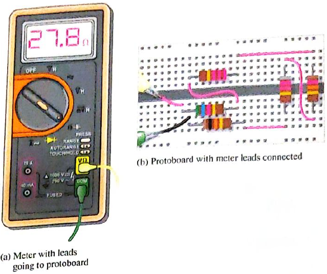
Is the multimeter reading in Figure 4-79 correct? If not, what is wrong?
Expert Solution & Answer
Want to see the full answer?
Check out a sample textbook solution
Students have asked these similar questions
Q1: Design a logic circuit for the finite-state machine described by the assigned
table in Fig. 1:
Using D flip-flops.
a.
b.
Using T flip-flops.
Present
Next State
Output
State
x=0
x=0
YE
Y₁Y
Y₁Y
Z
00
00
01
0
0
от
00
0
0
10
00
10
11
00
10
0
Find Va and Vb using mesh analysis
Find Va and Vb using Mesh analysis
Chapter 4 Solutions
Electronics Fundamentals: Circuits, Devices & Applications
Ch. 4 - A series circuit can have more than one path for...Ch. 4 - The total resistance of a series circuit can be...Ch. 4 - If two series resistors are different sizes, the...Ch. 4 - If two series resistors are different sizes, the...Ch. 4 - If three equal resistors are used in a voltage...Ch. 4 - Prob. 6TFQCh. 4 - Kirchhoff’s voltage law is valid only if a loop...Ch. 4 - Prob. 8TFQCh. 4 - Prob. 9TFQCh. 4 - If point A in a cricuit has a voltage of +10V and...
Ch. 4 - Prob. 1STCh. 4 - To measure the current out of the third resistor...Ch. 4 - Prob. 3STCh. 4 - When one of four series resistors is removed from...Ch. 4 - A series circuit consists of three resistors with...Ch. 4 - A 9 V battery is connected across a series...Ch. 4 - While putting four 1.5 V batteries in a...Ch. 4 - Prob. 8STCh. 4 - Prob. 9STCh. 4 - A series circuit consists of a 4.7k a 5.6k and a...Ch. 4 - Prob. 11STCh. 4 - Prob. 12STCh. 4 - When you connect an ammeter in a series resistive...Ch. 4 - While checking out a series resistive circuit, you...Ch. 4 - Determine the cause for each set of symptoms....Ch. 4 - Prob. 2TSCCh. 4 - Prob. 3TSCCh. 4 - Symptom: The ammeter reading is zero, voltmeter 1...Ch. 4 - Symptom: The ammeter reading is 0.645mA, the...Ch. 4 - Connect each set of resistors in Figure 4-64 in...Ch. 4 - Determine which resistors in Figure 4-65 are in...Ch. 4 - Determine the resistance between pins 1 and 8 in...Ch. 4 - Determine the resistance between pins 2 and 3 in...Ch. 4 - An 82 resistor and a 56 resistor are connected in...Ch. 4 - Find the total resistance of each group of series...Ch. 4 - Determine RT for each circuit in Figure 4-67. Show...Ch. 4 - What is the total resistance of twelve 5.6k...Ch. 4 - Six 47 resistors, eight 100 resistors, and two 22...Ch. 4 - The total resistance in Figure 4-68 is 20k. What...Ch. 4 - Determine the resistance between each of the...Ch. 4 - If all the resistors in Figure 4-65 are connected...Ch. 4 - What is the current through each of four resistors...Ch. 4 - The current from the source in Figure 4-69 is 5...Ch. 4 - What is the current in each circuit of Figure...Ch. 4 - 16. Determine the voltage across each resistor in...Ch. 4 - Three 470 resistors are in series with a 48 V...Ch. 4 - Four equal-value resitors are in series with a 5 V...Ch. 4 - Show how to connect four 6 V batteries to achieve...Ch. 4 - What happens if one of the batteries in Problem 19...Ch. 4 - The following voltage drops are measured across...Ch. 4 - Five resistors are in series with a 20 V source....Ch. 4 - Determine the unspecified voltage drop(s) in each...Ch. 4 - The total resistance of a series circuit is 500....Ch. 4 - Find the voltage between A and B in each voltage...Ch. 4 - Determine the voltage with respect to ground for...Ch. 4 - Determine the minimum and maximum output voltage...Ch. 4 - What is the voltage across each resistor in Figure...Ch. 4 - What is the voltage across each resistor on the...Ch. 4 - Five series resistors each dissipate 50 mW of...Ch. 4 - Find the total power in Figure 4-75.Ch. 4 - Prob. 32PCh. 4 - In Figure 4-77, how would you determine the...Ch. 4 - Determine the voltage at each point with respect...Ch. 4 - In Figure 4-77, what is VAC?Ch. 4 - In Figure 4-77, what is VCA?Ch. 4 - By observing the meters in Figure 4-78, determine...Ch. 4 - Is the multimeter reading in Figure 4-79 correct?...Ch. 4 - Determine the unknown resistance (R3) in the...Ch. 4 - You have the following resistor values available...Ch. 4 - Determine the voltage at each point in Figure 4-81...Ch. 4 - Find all the unknown quantities (shown in red) in...Ch. 4 - There are 250 mA in a series circuit with a total...Ch. 4 - Four 12W resistors are in series:...Ch. 4 - A certain series circuit is made up of a 18W...Ch. 4 - Using 1.5 V batteries, a switch, and three lamps,...Ch. 4 - Prob. 47PCh. 4 - Using the standard resistor values given in...Ch. 4 - On the double-sided PC board in Figure 4-83,...Ch. 4 - What is the total resistance from A to B for each...Ch. 4 - Determine the current measured by the meter in...Ch. 4 - Prob. 52PCh. 4 - Determine the voltage across each resistor in...Ch. 4 - Table 4-1 shows the results of resistance...Ch. 4 - You measure 15k between pins 5 and 6 on the PC...Ch. 4 - In checking out the PC board in Figure 4-83, you...Ch. 4 - The three groups of series resistors on the PC...Ch. 4 - Open file P04-58: Files are found at...Ch. 4 - Open file P04-59. Determine if there is a fault...Ch. 4 - Open file P04-60. Determine if there is a fault...Ch. 4 - Open file P04-61. Determine if there is a fault...Ch. 4 - Open file P04-62. Determine if there is a fault...Ch. 4 - www.prenhall.com/floyd. 63. Open file P04-63....
Knowledge Booster


Learn more about
Need a deep-dive on the concept behind this application? Look no further. Learn more about this topic, electrical-engineering and related others by exploring similar questions and additional content below.Similar questions
- Find Va and Vb using nodal analysisarrow_forward2. Using the approximate method, hand sketch the Bode plot for the following transfer functions. a) H(s) = 10 b) H(s) (s+1) c) H(s): = 1 = +1 100 1000 (s+1) 10(s+1) d) H(s) = (s+100) (180+1)arrow_forwardQ4: Write VHDL code to implement the finite-state machine described by the state Diagram in Fig. 1. Fig. 1arrow_forward
- 1. Consider the following feedback system. Bode plot of G(s) is shown below. Phase (deg) Magnitude (dB) -50 -100 -150 -200 0 -90 -180 -270 101 System: sys Frequency (rad/s): 0.117 Magnitude (dB): -74 10° K G(s) Bode Diagram System: sys Frequency (rad/s): 36.8 Magnitude (dB): -99.7 System: sys Frequency (rad/s): 20 Magnitude (dB): -89.9 System: sys Frequency (rad/s): 20 Phase (deg): -143 System: sys Frequency (rad/s): 36.8 Phase (deg): -180 101 Frequency (rad/s) a) Determine the range of K for which the closed-loop system is stable. 102 10³ b) If we want the gain margin to be exactly 50 dB, what is value for K we should choose? c) If we want the phase margin to be exactly 37°, what is value of K we should choose? What will be the corresponding rise time (T) for step-input? d) If we want steady-state error of step input to be 0.6, what is value of K we should choose?arrow_forward: Write VHDL code to implement the finite-state machine/described by the state Diagram in Fig. 4. X=1 X=0 solo X=1 X=0 $1/1 X=0 X=1 X=1 52/2 $3/3 X=1 Fig. 4 X=1 X=1 56/6 $5/5 X=1 54/4 X=0 X-O X=O 5=0 57/7arrow_forwardQuestions: Q1: Verify that the average power generated equals the average power absorbed using the simulated values in Table 7-2. Q2: Verify that the reactive power generated equals the reactive power absorbed using the simulated values in Table 7-2. Q3: Why it is important to correct the power factor of a load? Q4: Find the ideal value of the capacitor theoretically that will result in unity power factor. Vs pp (V) VRIPP (V) VRLC PP (V) AT (μs) T (us) 8° pf Simulated 14 8.523 7.84 84.850 1000 29.88 0.866 Measured 14 8.523 7.854 82.94 1000 29.85 0.86733 Table 7-2 Power Calculations Pvs (mW) Qvs (mVAR) PRI (MW) Pay (mW) Qt (mVAR) Qc (mYAR) Simulated -12.93 -7.428 9.081 3.855 12.27 -4.84 Calculated -12.936 -7.434 9.083 3.856 12.32 -4.85 Part II: Power Factor Correction Table 7-3 Power Factor Correction AT (us) 0° pf Simulated 0 0 1 Measured 0 0 1arrow_forward
- Questions: Q1: Verify that the average power generated equals the average power absorbed using the simulated values in Table 7-2. Q2: Verify that the reactive power generated equals the reactive power absorbed using the simulated values in Table 7-2. Q3: Why it is important to correct the power factor of a load? Q4: Find the ideal value of the capacitor theoretically that will result in unity power factor. Vs pp (V) VRIPP (V) VRLC PP (V) AT (μs) T (us) 8° pf Simulated 14 8.523 7.84 84.850 1000 29.88 0.866 Measured 14 8.523 7.854 82.94 1000 29.85 0.86733 Table 7-2 Power Calculations Pvs (mW) Qvs (mVAR) PRI (MW) Pay (mW) Qt (mVAR) Qc (mYAR) Simulated -12.93 -7.428 9.081 3.855 12.27 -4.84 Calculated -12.936 -7.434 9.083 3.856 12.32 -4.85 Part II: Power Factor Correction Table 7-3 Power Factor Correction AT (us) 0° pf Simulated 0 0 1 Measured 0 0 1arrow_forwardelectric plants. Prepare the load schedulearrow_forwardelectric plants Draw the column diagram. Calculate the voltage drop. by hand writingarrow_forward
- electric plants. Draw the lighting, socket, telephone, TV, and doorbell installations on the given single-story project with an architectural plan by hand writingarrow_forwardA circularly polarized wave, traveling in the +z-direction, is received by an elliptically polarized antenna whose reception characteristics near the main lobe are given approx- imately by E„ = [2â, + jâ‚]ƒ(r. 8, 4) Find the polarization loss factor PLF (dimensionless and in dB) when the incident wave is (a) right-hand (CW) An elliptically polarized wave traveling in the negative z-direction is received by a circularly polarized antenna. The vector describing the polarization of the incident wave is given by Ei= 2ax + jay.Find the polarization loss factor PLF (dimensionless and in dB) when the wave that would be transmitted by the antenna is (a) right-hand CParrow_forwardjX(1)=j0.2p.u. jXa(2)=j0.15p.u. jxa(0)=0.15 p.u. V₁=1/0°p.u. V₂=1/0° p.u. 1 jXr(1) = j0.15 p.11. jXT(2) = j0.15 p.u. jXr(0) = j0.15 p.u. V3=1/0° p.u. А V4=1/0° p.u. 2 jX1(1)=j0.12 p.u. 3 jX2(1)=j0.15 p.u. 4 jX1(2)=0.12 p.11. JX1(0)=0.3 p.u. jX/2(2)=j0.15 p.11. X2(0)=/0.25 p.1. Figure 1. Circuit for Q3 b).arrow_forward
arrow_back_ios
SEE MORE QUESTIONS
arrow_forward_ios
Recommended textbooks for you
 Electricity for Refrigeration, Heating, and Air C...Mechanical EngineeringISBN:9781337399128Author:Russell E. SmithPublisher:Cengage Learning
 Delmar's Standard Textbook Of ElectricityElectrical EngineeringISBN:9781337900348Author:Stephen L. HermanPublisher:Cengage Learning
Electricity for Refrigeration, Heating, and Air C...
Mechanical Engineering
ISBN:9781337399128
Author:Russell E. Smith
Publisher:Cengage Learning
Delmar's Standard Textbook Of Electricity
Electrical Engineering
ISBN:9781337900348
Author:Stephen L. Herman
Publisher:Cengage Learning
What is an electric furnace and how does it work?; Author: Fire & Ice Heating and Air Conditioning Inc;https://www.youtube.com/watch?v=wjAWecPGi0M;License: Standard Youtube License