
Electronics Fundamentals: Circuits, Devices & Applications
8th Edition
ISBN: 9780135072950
Author: Thomas L. Floyd, David Buchla
Publisher: Prentice Hall
expand_more
expand_more
format_list_bulleted
Concept explainers
Videos
Textbook Question
Chapter 4, Problem 41P
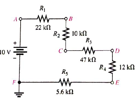
Determine the voltage at each point in Figure 4-81 with respect to ground.
Expert Solution & Answer
Want to see the full answer?
Check out a sample textbook solution
Students have asked these similar questions
Please draw out the circuits
Q2 but when you get to part 3, can you please draw it out
please solve manually. I need the drawing and the values too. Thank you!
Chapter 4 Solutions
Electronics Fundamentals: Circuits, Devices & Applications
Ch. 4 - A series circuit can have more than one path for...Ch. 4 - The total resistance of a series circuit can be...Ch. 4 - If two series resistors are different sizes, the...Ch. 4 - If two series resistors are different sizes, the...Ch. 4 - If three equal resistors are used in a voltage...Ch. 4 - Prob. 6TFQCh. 4 - Kirchhoff’s voltage law is valid only if a loop...Ch. 4 - Prob. 8TFQCh. 4 - Prob. 9TFQCh. 4 - If point A in a cricuit has a voltage of +10V and...
Ch. 4 - Prob. 1STCh. 4 - To measure the current out of the third resistor...Ch. 4 - Prob. 3STCh. 4 - When one of four series resistors is removed from...Ch. 4 - A series circuit consists of three resistors with...Ch. 4 - A 9 V battery is connected across a series...Ch. 4 - While putting four 1.5 V batteries in a...Ch. 4 - Prob. 8STCh. 4 - Prob. 9STCh. 4 - A series circuit consists of a 4.7k a 5.6k and a...Ch. 4 - Prob. 11STCh. 4 - Prob. 12STCh. 4 - When you connect an ammeter in a series resistive...Ch. 4 - While checking out a series resistive circuit, you...Ch. 4 - Determine the cause for each set of symptoms....Ch. 4 - Prob. 2TSCCh. 4 - Prob. 3TSCCh. 4 - Symptom: The ammeter reading is zero, voltmeter 1...Ch. 4 - Symptom: The ammeter reading is 0.645mA, the...Ch. 4 - Connect each set of resistors in Figure 4-64 in...Ch. 4 - Determine which resistors in Figure 4-65 are in...Ch. 4 - Determine the resistance between pins 1 and 8 in...Ch. 4 - Determine the resistance between pins 2 and 3 in...Ch. 4 - An 82 resistor and a 56 resistor are connected in...Ch. 4 - Find the total resistance of each group of series...Ch. 4 - Determine RT for each circuit in Figure 4-67. Show...Ch. 4 - What is the total resistance of twelve 5.6k...Ch. 4 - Six 47 resistors, eight 100 resistors, and two 22...Ch. 4 - The total resistance in Figure 4-68 is 20k. What...Ch. 4 - Determine the resistance between each of the...Ch. 4 - If all the resistors in Figure 4-65 are connected...Ch. 4 - What is the current through each of four resistors...Ch. 4 - The current from the source in Figure 4-69 is 5...Ch. 4 - What is the current in each circuit of Figure...Ch. 4 - 16. Determine the voltage across each resistor in...Ch. 4 - Three 470 resistors are in series with a 48 V...Ch. 4 - Four equal-value resitors are in series with a 5 V...Ch. 4 - Show how to connect four 6 V batteries to achieve...Ch. 4 - What happens if one of the batteries in Problem 19...Ch. 4 - The following voltage drops are measured across...Ch. 4 - Five resistors are in series with a 20 V source....Ch. 4 - Determine the unspecified voltage drop(s) in each...Ch. 4 - The total resistance of a series circuit is 500....Ch. 4 - Find the voltage between A and B in each voltage...Ch. 4 - Determine the voltage with respect to ground for...Ch. 4 - Determine the minimum and maximum output voltage...Ch. 4 - What is the voltage across each resistor in Figure...Ch. 4 - What is the voltage across each resistor on the...Ch. 4 - Five series resistors each dissipate 50 mW of...Ch. 4 - Find the total power in Figure 4-75.Ch. 4 - Prob. 32PCh. 4 - In Figure 4-77, how would you determine the...Ch. 4 - Determine the voltage at each point with respect...Ch. 4 - In Figure 4-77, what is VAC?Ch. 4 - In Figure 4-77, what is VCA?Ch. 4 - By observing the meters in Figure 4-78, determine...Ch. 4 - Is the multimeter reading in Figure 4-79 correct?...Ch. 4 - Determine the unknown resistance (R3) in the...Ch. 4 - You have the following resistor values available...Ch. 4 - Determine the voltage at each point in Figure 4-81...Ch. 4 - Find all the unknown quantities (shown in red) in...Ch. 4 - There are 250 mA in a series circuit with a total...Ch. 4 - Four 12W resistors are in series:...Ch. 4 - A certain series circuit is made up of a 18W...Ch. 4 - Using 1.5 V batteries, a switch, and three lamps,...Ch. 4 - Prob. 47PCh. 4 - Using the standard resistor values given in...Ch. 4 - On the double-sided PC board in Figure 4-83,...Ch. 4 - What is the total resistance from A to B for each...Ch. 4 - Determine the current measured by the meter in...Ch. 4 - Prob. 52PCh. 4 - Determine the voltage across each resistor in...Ch. 4 - Table 4-1 shows the results of resistance...Ch. 4 - You measure 15k between pins 5 and 6 on the PC...Ch. 4 - In checking out the PC board in Figure 4-83, you...Ch. 4 - The three groups of series resistors on the PC...Ch. 4 - Open file P04-58: Files are found at...Ch. 4 - Open file P04-59. Determine if there is a fault...Ch. 4 - Open file P04-60. Determine if there is a fault...Ch. 4 - Open file P04-61. Determine if there is a fault...Ch. 4 - Open file P04-62. Determine if there is a fault...Ch. 4 - www.prenhall.com/floyd. 63. Open file P04-63....
Knowledge Booster


Learn more about
Need a deep-dive on the concept behind this application? Look no further. Learn more about this topic, electrical-engineering and related others by exploring similar questions and additional content below.Similar questions
- Two alternators, Y-connected 6.6 kV supply a load of 3000 kW at 0.8 p.f lagging. The synchronous mpedance of first alternator is (0.5+j10) Q/ph and second alternator is (0.4+j12) /ph. First alternator delivers 150 amp at 0.875 lag p.f. The two alterators are shared load equally. Determine the current, p.f., induced e.m.f, load angel, and maximum developed power of each alternator?arrow_forwardA domestic load of 2300 kW at 0.88 p.f lagging and a motors load of 3400 kW at 0.85 p.f lagging are supplied by two alternators operating in parallel. If one alternator is delivering a load of 3300 kW at 0.9 p.f lagging, what will be the output power and p.f of the other alternator?arrow_forwardDetermine the value of Rr that necessary for the circuit in Fig.(2) to operate as an oscillator and then determine the frequency of oscillation. 0.001 F 0.001 F 0.001 F R₁ • 10 ΚΩ R₁ 10 k R • 10 ΚΩarrow_forward
- (a) For the circuit shown in Figure Q3(a) (RFC and Cc are forbias) (i) (ii) Draw the AC small signal equivalent circuit of the oscillator. From this equivalent circuit derive an equation for fo and the gain condition for the oscillations to start. VDD www RG eee RFC H Cc 北 5 C₁ L 000 C₂ Voarrow_forwardPlease solve this question step by step handwritten solution and do not use chat gpt or any ai toolsfor part ii) you may need to use nodal analysisarrow_forward12.1. Find the steady-state response vo (t) for the network. 00000- 1Ω ww 12 cos(t) V + www 202 1 H 202 1 F + 1Ω νο -arrow_forward
- A Three-phase, 12 pole, Y-connected alternator has 108 slots and 14 conductors per slot. The windings are (5/6 th) pitched. The flux per pole is 57 mWb distributed sinusoidally over the pole. If the machine runs at 500 r.p.m., determine the following: (a) The frequency of the generated e.m.f., (b) The distribution factor, (c) The pitch factor, and (d) The phase and line values of the generated e.m.f.?arrow_forwardTwo 3-ph, 6.6 kV, Y-connected, alternators supply a load of 3000 kW at 0.8 p.f. lagging. The synchronou impedance per phase of machine A is (0.5+110) and that of machine B is (0.4 +J12) . The excitation of machine A adjusted so that it delivers 150 A. The load is shared equally between the machines. Determine the armature curre p.f., induced e.m.f., and load angle of each machine?arrow_forwardName the circuit below? The output voltage is initially zero and the pulse width is 200 μs. Find the Vout and draw the output waveform? +2.5 V V 247 -2.5 V C 0.01 F Ri W 10 ΚΩarrow_forward
- Please work outarrow_forwardFind Vfinal when Vs up and Vs V. Which LED will light in each case? Red or Green? Justify your answers. Fill the table below. Vs 8 ΚΩ Vos Χρι + 3 ΚΩ www 6 ΚΩ ww 4 ΚΩ Yo www Vo Vec-12 V Nol V final Vm w 3 ΚΩ 5 V 38 ΚΩ R= 1 kQ V -12 V Red LED Green LED Vs Vo Vfinal Which LED is ON? Varrow_forwardCircuits help please solve and explain. Question in images providedarrow_forward
arrow_back_ios
SEE MORE QUESTIONS
arrow_forward_ios
Recommended textbooks for you
 Electricity for Refrigeration, Heating, and Air C...Mechanical EngineeringISBN:9781337399128Author:Russell E. SmithPublisher:Cengage Learning
 Delmar's Standard Textbook Of ElectricityElectrical EngineeringISBN:9781337900348Author:Stephen L. HermanPublisher:Cengage Learning
Electricity for Refrigeration, Heating, and Air C...
Mechanical Engineering
ISBN:9781337399128
Author:Russell E. Smith
Publisher:Cengage Learning
Delmar's Standard Textbook Of Electricity
Electrical Engineering
ISBN:9781337900348
Author:Stephen L. Herman
Publisher:Cengage Learning
What is an electric furnace and how does it work?; Author: Fire & Ice Heating and Air Conditioning Inc;https://www.youtube.com/watch?v=wjAWecPGi0M;License: Standard Youtube License