
Electronics Fundamentals: Circuits, Devices & Applications
8th Edition
ISBN: 9780135072950
Author: Thomas L. Floyd, David Buchla
Publisher: Prentice Hall
expand_more
expand_more
format_list_bulleted
Concept explainers
Videos
Textbook Question
Chapter 4, Problem 50P
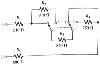
What is the total resistance from A to B for each switch position in Figure 4-84?
Expert Solution & Answer
Want to see the full answer?
Check out a sample textbook solution
Students have asked these similar questions
Consider a particle confined in an infinite potential well as shown below and its wave function
Solve the following problems.
is derived as √(x) = A sin (TA), and energy E=
H
U
0
U=0
a
x
πλη
2ma²
€30
(iii)
Calculate the value of A. [Hint: The probability of finding the particle in 0
Q2: Using D flip-flops, design a synchronous counter. The counter counts in the sequence
1,3,5,7, 1,7,5,3,1,3,5,7,.... when its enable input x is equal to 1; otherwise, the counter
count 0.
8.19 In the circuit shown in Fig. P8.19, u(t) = 40cos(105t) V,R1 = 100 W, R2 = 500 W, C = 0.1 μF, and L = 0.5 mH.Determine the complex power for each passive element, and verifythat conservation of energy is satisfied.
Chapter 4 Solutions
Electronics Fundamentals: Circuits, Devices & Applications
Ch. 4 - A series circuit can have more than one path for...Ch. 4 - The total resistance of a series circuit can be...Ch. 4 - If two series resistors are different sizes, the...Ch. 4 - If two series resistors are different sizes, the...Ch. 4 - If three equal resistors are used in a voltage...Ch. 4 - Prob. 6TFQCh. 4 - Kirchhoff’s voltage law is valid only if a loop...Ch. 4 - Prob. 8TFQCh. 4 - Prob. 9TFQCh. 4 - If point A in a cricuit has a voltage of +10V and...
Ch. 4 - Prob. 1STCh. 4 - To measure the current out of the third resistor...Ch. 4 - Prob. 3STCh. 4 - When one of four series resistors is removed from...Ch. 4 - A series circuit consists of three resistors with...Ch. 4 - A 9 V battery is connected across a series...Ch. 4 - While putting four 1.5 V batteries in a...Ch. 4 - Prob. 8STCh. 4 - Prob. 9STCh. 4 - A series circuit consists of a 4.7k a 5.6k and a...Ch. 4 - Prob. 11STCh. 4 - Prob. 12STCh. 4 - When you connect an ammeter in a series resistive...Ch. 4 - While checking out a series resistive circuit, you...Ch. 4 - Determine the cause for each set of symptoms....Ch. 4 - Prob. 2TSCCh. 4 - Prob. 3TSCCh. 4 - Symptom: The ammeter reading is zero, voltmeter 1...Ch. 4 - Symptom: The ammeter reading is 0.645mA, the...Ch. 4 - Connect each set of resistors in Figure 4-64 in...Ch. 4 - Determine which resistors in Figure 4-65 are in...Ch. 4 - Determine the resistance between pins 1 and 8 in...Ch. 4 - Determine the resistance between pins 2 and 3 in...Ch. 4 - An 82 resistor and a 56 resistor are connected in...Ch. 4 - Find the total resistance of each group of series...Ch. 4 - Determine RT for each circuit in Figure 4-67. Show...Ch. 4 - What is the total resistance of twelve 5.6k...Ch. 4 - Six 47 resistors, eight 100 resistors, and two 22...Ch. 4 - The total resistance in Figure 4-68 is 20k. What...Ch. 4 - Determine the resistance between each of the...Ch. 4 - If all the resistors in Figure 4-65 are connected...Ch. 4 - What is the current through each of four resistors...Ch. 4 - The current from the source in Figure 4-69 is 5...Ch. 4 - What is the current in each circuit of Figure...Ch. 4 - 16. Determine the voltage across each resistor in...Ch. 4 - Three 470 resistors are in series with a 48 V...Ch. 4 - Four equal-value resitors are in series with a 5 V...Ch. 4 - Show how to connect four 6 V batteries to achieve...Ch. 4 - What happens if one of the batteries in Problem 19...Ch. 4 - The following voltage drops are measured across...Ch. 4 - Five resistors are in series with a 20 V source....Ch. 4 - Determine the unspecified voltage drop(s) in each...Ch. 4 - The total resistance of a series circuit is 500....Ch. 4 - Find the voltage between A and B in each voltage...Ch. 4 - Determine the voltage with respect to ground for...Ch. 4 - Determine the minimum and maximum output voltage...Ch. 4 - What is the voltage across each resistor in Figure...Ch. 4 - What is the voltage across each resistor on the...Ch. 4 - Five series resistors each dissipate 50 mW of...Ch. 4 - Find the total power in Figure 4-75.Ch. 4 - Prob. 32PCh. 4 - In Figure 4-77, how would you determine the...Ch. 4 - Determine the voltage at each point with respect...Ch. 4 - In Figure 4-77, what is VAC?Ch. 4 - In Figure 4-77, what is VCA?Ch. 4 - By observing the meters in Figure 4-78, determine...Ch. 4 - Is the multimeter reading in Figure 4-79 correct?...Ch. 4 - Determine the unknown resistance (R3) in the...Ch. 4 - You have the following resistor values available...Ch. 4 - Determine the voltage at each point in Figure 4-81...Ch. 4 - Find all the unknown quantities (shown in red) in...Ch. 4 - There are 250 mA in a series circuit with a total...Ch. 4 - Four 12W resistors are in series:...Ch. 4 - A certain series circuit is made up of a 18W...Ch. 4 - Using 1.5 V batteries, a switch, and three lamps,...Ch. 4 - Prob. 47PCh. 4 - Using the standard resistor values given in...Ch. 4 - On the double-sided PC board in Figure 4-83,...Ch. 4 - What is the total resistance from A to B for each...Ch. 4 - Determine the current measured by the meter in...Ch. 4 - Prob. 52PCh. 4 - Determine the voltage across each resistor in...Ch. 4 - Table 4-1 shows the results of resistance...Ch. 4 - You measure 15k between pins 5 and 6 on the PC...Ch. 4 - In checking out the PC board in Figure 4-83, you...Ch. 4 - The three groups of series resistors on the PC...Ch. 4 - Open file P04-58: Files are found at...Ch. 4 - Open file P04-59. Determine if there is a fault...Ch. 4 - Open file P04-60. Determine if there is a fault...Ch. 4 - Open file P04-61. Determine if there is a fault...Ch. 4 - Open file P04-62. Determine if there is a fault...Ch. 4 - www.prenhall.com/floyd. 63. Open file P04-63....
Knowledge Booster


Learn more about
Need a deep-dive on the concept behind this application? Look no further. Learn more about this topic, electrical-engineering and related others by exploring similar questions and additional content below.Similar questions
- In the circuit shown, let R₁=7, R₂=12, R3=24, R4-2, V₁ =26, V2=104, and V3-78, to calculate the power delivered (or absorbed) by the circuit inside the box, as follows: {NOTE: On Multiple Choice Questions, like this problem, you have only one attempt } 1. The current I is equal to (choose the closed values in amperes) O 1.156 -1.156 -1.209 -4.622 1.209 0 (A) 4.622 2. The power delivered (or absorbed) (choose the closest value in watts) (W) -873.292 152.225 O 873.292 -122.181 -58.086 0 O 122.181 R₁ ww V₂ R₂ R3 V1 ww R4 √3arrow_forwardFor the circuit shown, find the currents 11, 12, 16 and 17, given 13 =1 A, 14-19 A, 15 =-10 A, and Ig =5 A. = (A) 12 = (A) 16 = (A) 175 (A) (Based on Alexander Textbook, Chapter2) I5 12 14 18 13 16 • Round your values to 3-significant digits.arrow_forwardIn the circuit shown, let R₁=62, R2=39, R3=16, R4-7 and V5-194, to calculate Vo and lo, as follows: V₁ R1 R3 Find the overall current i delivered by the voltage source Vs: • Find the voltage Vo: • Find the current l₁ : The relative tolerance for this problem is 7 %. (V) (A) www. R₂ + RA (A)arrow_forward
- For the circuit shown, let V₁ =35 V, V₂-7 V, and R=45 $2, ⚫ The current I = • The power absorbed by the resistor R; PR (A) find: • The power delivered/absorbed by the voltage source V₁; Pv₁= ⚫ The power delivered/absorbed by the voltage source V2; Pv2= ⚫ The power delivered/absorbed by the voltage source (-8V); P-8 = V₁ (1+ √2 + (+ −8 V (W) (W) (W) (W) Rarrow_forwardUsing simulation in MATLAB and show the results signal.arrow_forwardAn elliptically polarized wave traveling in -ve z-direction is received by circularly polarized antenna. 11 the unit vector of the incident wave is w = wave would be right hand CP. 2âx-jay. Find PLF (dimensionless) when the transmittedarrow_forward
- An elliptically polarized wave traveling in the negative z-direction is received by a circularly polarized antenna. The vector describing the polarization of the incident wave is given by Ei= 2ax + jay .Find the polarization loss factor PLF (dimensionless and in dB) when the wave that would be transmitted by the antenna is (a) right-hand CP (b) left-hand CP.arrow_forwardFind V show all stepsarrow_forwardA wave radiated by an antenna is traveling in the outward radial direction along the +z axis. Its radiated field in the far zone region is described by its spherical components, and its polarization is right-hand (clockwise) circularly polarized. This radiated field impinging upon a receiving antenna whose polarization is also right-hand (clockwise) circularly polarized and whose polarization unit vector is represented by (ao-jas) E₁ = E(7,0,0) (0-100) Determine the polarization loss factor (PLF)arrow_forward
- Find V0, it's an ideal Op-amparrow_forwardFjjrjarrow_forwardHW_#1 HW_01.pdf EE 213-01 Assignments P Pearson MyLab and Mastering uah.instructure.com P Course Home Watch out for units (i.e, kQ, mA, etc), show all units on answers and clearly mark all answers 1)(5 pts) Specify if the following elements are absorbing or delivering power, and determine the amount of power being absorbed or delivered. 10 V + a) 5A + 5 V - b) 2A + 10 V -2A 2)(5 pts) Two circuits, shown by boxes A and B are connected as shown below. Use the current reference direction provided and the voltage reference polarity shown to determine the power for the interconnection. Also state the direction of power flow for the connection: form A to B or B to A. A I + I a) I = -6 A V = -20 Volts b) 1 = 8 A V = 30 Volts c) = 4 A V = -80 Volts d) I = -5 A V = 40 Volts B 3) (5 pts) Use Ohm's Law, KCL and KVL to determine values for V1, V2, V₁, I₁, and I2. 200 Ohms A, + 12 + V1 75 Ohms 3 Amps + V2 300 Ohms 25 Ohms 4) (5 pts) For the circuit in Problem 2, determine the power (expressed as a…arrow_forward
arrow_back_ios
SEE MORE QUESTIONS
arrow_forward_ios
Recommended textbooks for you
 Electricity for Refrigeration, Heating, and Air C...Mechanical EngineeringISBN:9781337399128Author:Russell E. SmithPublisher:Cengage Learning
 Delmar's Standard Textbook Of ElectricityElectrical EngineeringISBN:9781337900348Author:Stephen L. HermanPublisher:Cengage Learning
Electricity for Refrigeration, Heating, and Air C...
Mechanical Engineering
ISBN:9781337399128
Author:Russell E. Smith
Publisher:Cengage Learning
Delmar's Standard Textbook Of Electricity
Electrical Engineering
ISBN:9781337900348
Author:Stephen L. Herman
Publisher:Cengage Learning
Electrical Measuring Instruments - Testing Equipment Electrical - Types of Electrical Meters; Author: Learning Engineering;https://www.youtube.com/watch?v=gkeJzRrwe5k;License: Standard YouTube License, CC-BY
01 - Instantaneous Power in AC Circuit Analysis (Electrical Engineering); Author: Math and Science;https://www.youtube.com/watch?v=If25y4Nhvw4;License: Standard YouTube License, CC-BY