
Fundamentals of Electric Circuits
6th Edition
ISBN: 9780078028229
Author: Charles K Alexander, Matthew Sadiku
Publisher: McGraw-Hill Education
expand_more
expand_more
format_list_bulleted
Concept explainers
Videos
Textbook Question
Chapter 4, Problem 2P
Using Fig. 4.70, design a problem to help other students better understand linearity.
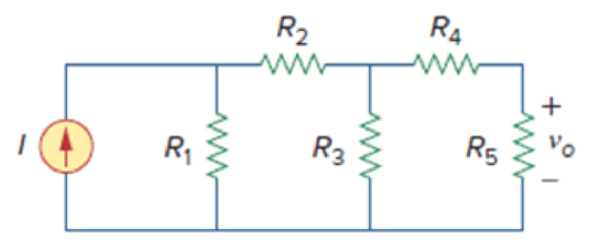
Figure 4.70
Expert Solution & Answer
Want to see the full answer?
Check out a sample textbook solution
Students have asked these similar questions
For the circuit shown, find
(i) closed-loop voltage gain
(ii) Z i of the circuit
(iii) f_max. The slew rate is 0.6V/us.
((write your answer in Kilo ohm))
2Vpp
R
ww
20 kQ
R₁
ww
200 ΚΩ
9+18 V
- 18 V
10 kn R₁₂
ΚΩ
((write your answer in KHz))
illustrate the phenomenon of phase reversal in CE amplifier
i- When signal current =OA, so IB-8uA
ii- When input signal reaches positive peak, so IB=16uA
ii- When input signal reaches negative peak, so IB=4uA
R₁
www
+ Vcc = 12V
Rc=6kn
16 A
8 μA
4 μА
0
www
RE
ẞ = 100
VC
In the circuit shown, find the voltage gain. Given that ẞ = 80 and input resistance Rin=2kQ.
SIGNAL
+10 V
Rc=6kn
4-2
210
Chapter 4 Solutions
Fundamentals of Electric Circuits
Ch. 4.2 - Figure 4.3 For Practice Prob. 4.1. For the circuit...Ch. 4.2 - Figure 4.5 For Practice Prob. 4.2. Assume that Vo...Ch. 4.3 - Figure 4.8 Using the superposition theorem, find...Ch. 4.3 - Figure 4.11 Use superposition to find vx in the...Ch. 4.3 - Find I in the circuit of Fig. 4.14 using the...Ch. 4.4 - Find io in the circuit of Fig. 4.19 using source...Ch. 4.4 - Use source transformation to find ix in the...Ch. 4.5 - Using Thevenins theorem, find the equivalent...Ch. 4.5 - Find the Thevenin equivalent circuit of the...Ch. 4.5 - Obtain the Thevenin equivalent of the circuit in...
Ch. 4.6 - Find the Norton equivalent circuit for the circuit...Ch. 4.6 - Find the Norton equivalent circuit of the circuit...Ch. 4.8 - Determine the value of RL that will draw the...Ch. 4.9 - Rework Practice Prob. 4.9 using PSpice. Find the...Ch. 4.9 - Fin d the maximum power transferred to RL if the...Ch. 4.10 - The measured open-circuit voltage across a certain...Ch. 4.10 - Prob. 17PPCh. 4.10 - Obtain the current through the galvanometer,...Ch. 4 - The current through a branch in a linear network...Ch. 4 - For superposition, it is not required that only...Ch. 4 - The superposition principle applies to power...Ch. 4 - Refer to Fig. 4.67. The Thevenin resistance at...Ch. 4 - The Thevenin voltage across terminals a and b of...Ch. 4 - The Norton current at terminals a and b of the...Ch. 4 - The Norton resistance RN is exactly equal to the...Ch. 4 - Which pair of circuits in Fig. 4.68 are...Ch. 4 - A load is connected to a network. At the terminals...Ch. 4 - The source is supplying the maximum power to the...Ch. 4 - Calculate the current io in the circuit of Fig....Ch. 4 - Using Fig. 4.70, design a problem to help other...Ch. 4 - (a) In the circuit of Fig. 4.71, calculate vo and...Ch. 4 - Use linearity to determine io in the circuit of...Ch. 4 - For the circuit in Fig. 4.73, assume vo = 1 V, and...Ch. 4 - For the linear circuit shown in Fig. 4.74, use...Ch. 4 - Use linearity and the assumption that Vo = 1 V to...Ch. 4 - Using superposition, find Vo in the circuit of...Ch. 4 - Given that I = 6 amps when Vs = 160 volts and Is =...Ch. 4 - Using Fig. 4.78, design a problem to help other...Ch. 4 - Use the superposition principle to find io and vo...Ch. 4 - Determine vo in the circuit of Fig. 4.80 using the...Ch. 4 - Use superposition to find vo in the circuit of...Ch. 4 - Apply the superposition principle to find vo in...Ch. 4 - For the circuit in Fig. 4.83, use superposition to...Ch. 4 - Given the circuit in Fig. 4.84, use superposition...Ch. 4 - Use superposition to obtain vx in the circuit of...Ch. 4 - Use superposition to find Vo in the circuit of...Ch. 4 - Use superposition to solve for vx in the circuit...Ch. 4 - Use source transformation to reduce the circuit...Ch. 4 - Using Fig. 4.89, design a problem to help other...Ch. 4 - For the circuit in Fig, 4.90, use source...Ch. 4 - Referring to Fig. 4.91, use source transformation...Ch. 4 - Use source transformation to find the voltage Vx...Ch. 4 - Obtain vo in the circuit of Fig. 4.93 using source...Ch. 4 - Use source transformation to find io in the...Ch. 4 - Apply source transformation to find vx in the...Ch. 4 - Use source transformation to find Io in Fig. 4.96....Ch. 4 - Use source transformation to find vo in the...Ch. 4 - Use source transformation on the circuit shown in...Ch. 4 - Determine vx in the circuit of Fig. 4.99 using...Ch. 4 - Use source transformation to find ix in the...Ch. 4 - Determine the Thevenin equivalent circuit, shown...Ch. 4 - Using Fig. 4.102, design a problem that will help...Ch. 4 - Use Thevenins theorem to find vo in Prob. 4.12....Ch. 4 - Solve for the current i in the circuit of Fig....Ch. 4 - Find the Norton equivalent with respect to...Ch. 4 - Apply Thevenins theorem to find Vo in the circuit...Ch. 4 - Obtain the Thevenin equivalent at terminals a-b of...Ch. 4 - Find the Thevenin equivalent at terminals a-b of...Ch. 4 - Find the Thevenin and Norton equivalents at...Ch. 4 - For the circuit in Fig. 4.109, find the Thevenin...Ch. 4 - Find the Thevenin equivalent looking into...Ch. 4 - For the circuit in Fig. 4.111, obtain the Thevenin...Ch. 4 - Find the Thevenin equivalent of the circuit in...Ch. 4 - Using Fig. 4.113, design a problem to help other...Ch. 4 - Obtain the Thevenin and Norton equivalent circuits...Ch. 4 - Determine the Norton equivalent at terminals a-b...Ch. 4 - Find the Norton equivalent looking into terminals...Ch. 4 - Obtain the Norton equivalent of the circuit in...Ch. 4 - Given the circuit in Fig. 4.117, obtain the Norton...Ch. 4 - For the transistor model in Fig. 4.118, obtain the...Ch. 4 - Find the Norton equivalent at terminals a-b of the...Ch. 4 - Find the Thevenin equivalent between terminals a-b...Ch. 4 - Obtain the Norton equivalent at terminals a-b of...Ch. 4 - Use Nortons theorem to find Vo in the circuit of...Ch. 4 - Obtain the Thevenin and Norton equivalent circuits...Ch. 4 - The network in Fig. 4.124 models a bipolar...Ch. 4 - Determine the Thevenin and Norton equivalents at...Ch. 4 - For the circuit in Fig. 4.126, find the Thevenin...Ch. 4 - Obtain the Thevenin and Norton equivalent circuits...Ch. 4 - Find the Thevenin equivalent of the circuit in...Ch. 4 - Find the Norton equivalent for the circuit in Fig....Ch. 4 - Obtain the Thevenin equivalent seen at terminals...Ch. 4 - For the circuit shown in Fig. 4.131, determine the...Ch. 4 - Find the maximum power that can be delivered to...Ch. 4 - The variable resistor R in Fig. 4.133 is adjusted...Ch. 4 - Consider the 30- resistor in Fig. 4.134. First...Ch. 4 - Find the maximum power transferred to resistor R...Ch. 4 - Determine the maximum power delivered to the...Ch. 4 - For the circuit in Fig. 4.137, what resistor...Ch. 4 - (a) For the circuit in Fig. 4.138, obtain the...Ch. 4 - Determine the maximum power that can be delivered...Ch. 4 - For the bridge circuit shown in Fig. 4.140, find...Ch. 4 - For the circuit in Fig. 4.141, determine the value...Ch. 4 - Solve Prob. 4.34 using PSpice or MultiSim. Let V =...Ch. 4 - Use PSpice or MultiSim to solve Prob. 4.44. For...Ch. 4 - Use PSpice or MultiSim to solve Prob. 4.52.Ch. 4 - Obtain the Thevenin equivalent of the circuit in...Ch. 4 - Use PSpice or MultiSim to find the Thevenin...Ch. 4 - For the circuit in Fig. 4.126, use PSpice or...Ch. 4 - An automobile battery has an open circuit voltage...Ch. 4 - The following results were obtained from...Ch. 4 - When connected to a 4- resistor, a battery has a...Ch. 4 - The Thevenin equivalent at terminals a-b of the...Ch. 4 - A black box with a circuit in it is connected to a...Ch. 4 - A transducer is modeled with a current source Is...Ch. 4 - Consider the circuit in Fig. 4.144. An ammeter...Ch. 4 - Consider the circuit in Fig. 4.145. (a) Replace...Ch. 4 - The Wheatstone bridge circuit shown in Fig. 4.146...Ch. 4 - (a) In the Wheatstone bridge circuit of Fig. 4.147...Ch. 4 - Consider the bridge circuit of Fig. 4.148. Is the...Ch. 4 - The circuit in Fig. 4.149 models a common-emitter...Ch. 4 - An attenuator is an interface circuit that reduces...Ch. 4 - A dc voltmeter with a sensitivity of 10 k/V is...Ch. 4 - A resistance array is connected to a load resistor...Ch. 4 - A common-emitter amplifier circuit is shown in...Ch. 4 - For Practice Prob. 4.18, determine the current...
Knowledge Booster


Learn more about
Need a deep-dive on the concept behind this application? Look no further. Learn more about this topic, electrical-engineering and related others by exploring similar questions and additional content below.Similar questions
- For the transistor amplifier shown, R₁-11kQ, R2=6kQ, Rc=2kQ, RE-3kQ and R₁=2k0. (i) Draw d.c. load line (ii) Determine the DC operating point (iii) Draw a.c. load line. Assume V_BE = 0.7 V. and determine the new operating point + Vcc = 15 V RC Cc Cin R1 wwwwww wwwww R₁₂ RE CE RLarrow_forwardthe first part is the second part write your answer such as: (AND, OR, INVERTER, NAND, NOR) D₁ AK D, R₁ B K First Part? the third part is , and the total are R4 R7 Output R5 R₁ T R6 R3 -UBB Second Part? Third Part? Total?arrow_forwardA multistage amplifier has six stages each of which has a power gain of 40. what is the - Total gain of the amplifier in db ? ii- If the negative feedback of 15db is employed, find the resultant gainarrow_forward
- 9.36 Consider the finite-state machine logic implementation in Figure P9.36. (a) Determine the next-state and output logic expressions. (b) Determine the number of possible states. J1 Clk K₁ 101 Ут J2 Clk K₂ Clk Figure P9.36 0 y2 10arrow_forward9.34 Consider the finite-state machine logic implementation in Figure P9.34. (a) Determine the next-state and output logic expressions. (b) Determine the number of possible states. (c) Construct a state assigned table. (d) Construct a state table. (e) Construct a state diagram. (f) Determine the function of the finite-state machine. T₁ x Clk Figure P9.34 Q Clk Q الا T₂ Q 32 Clk Q T3 Q Clk Q Узarrow_forward9.35 Consider the finite-state machine logic implementation in Figure P9.35. (a) Determine the next-state and output logic expressions. (b) Determine the number of possible states. (c) Construct a state assigned table. (d) Construct a state table. (e) Construct a state diagram. (f) Determine the function of the finite-state machine. Clk J Clk K₁ 10 Ут J2 Clk K₂ 10 32 Figure P9.35arrow_forward
- 9.56 Using JK flip-flops, design a synchronous counter that counts in the sequence 1, 3, 0, 2, 1, ... The counter counts only when its enable input x is equal to 1; otherwise, the counter is idle.arrow_forward9.65 Using T flip-flops, design a synchronous counter that counts in the sequence 0, 2, 4, 6, 0, ... The counter counts only when its enable input x is equal to 1; otherwise, the counter is idle.arrow_forward2 Using D flip-flops, design a synchronous counter that counts in the sequence 1, 4, 7, 1, The counter counts only when its enable input x is equal to 1; otherwise, the counter is idle.arrow_forward
- Q1: Write a VHDL code to implement the finite state machine described in the state diagram shown below. Clk D 0 CIK Q D 0 Cik Q =arrow_forwardQ1: Consider the finite state machine logic implementation in Fig. shown below: Construct the state diagram. Repeat the circuit design using j-k flip flop. r" Clk Y D' Y, Clk Q D Clk 10 0 22 3'2arrow_forwardQ: Write a VHDL code to implement the finite state machine described in the state diagram shown below. T 2 Clk Q Clk T₂ 0 la Clk T3 Q Cik 0arrow_forward
arrow_back_ios
SEE MORE QUESTIONS
arrow_forward_ios
Recommended textbooks for you
 Introductory Circuit Analysis (13th Edition)Electrical EngineeringISBN:9780133923605Author:Robert L. BoylestadPublisher:PEARSON
 Delmar's Standard Textbook Of ElectricityElectrical EngineeringISBN:9781337900348Author:Stephen L. HermanPublisher:Cengage Learning
 Programmable Logic ControllersElectrical EngineeringISBN:9780073373843Author:Frank D. PetruzellaPublisher:McGraw-Hill Education
 Fundamentals of Electric CircuitsElectrical EngineeringISBN:9780078028229Author:Charles K Alexander, Matthew SadikuPublisher:McGraw-Hill Education
 Electric Circuits. (11th Edition)Electrical EngineeringISBN:9780134746968Author:James W. Nilsson, Susan RiedelPublisher:PEARSON
 Engineering ElectromagneticsElectrical EngineeringISBN:9780078028151Author:Hayt, William H. (william Hart), Jr, BUCK, John A.Publisher:Mcgraw-hill Education,
Introductory Circuit Analysis (13th Edition)
Electrical Engineering
ISBN:9780133923605
Author:Robert L. Boylestad
Publisher:PEARSON
Delmar's Standard Textbook Of Electricity
Electrical Engineering
ISBN:9781337900348
Author:Stephen L. Herman
Publisher:Cengage Learning
Programmable Logic Controllers
Electrical Engineering
ISBN:9780073373843
Author:Frank D. Petruzella
Publisher:McGraw-Hill Education
Fundamentals of Electric Circuits
Electrical Engineering
ISBN:9780078028229
Author:Charles K Alexander, Matthew Sadiku
Publisher:McGraw-Hill Education
Electric Circuits. (11th Edition)
Electrical Engineering
ISBN:9780134746968
Author:James W. Nilsson, Susan Riedel
Publisher:PEARSON
Engineering Electromagnetics
Electrical Engineering
ISBN:9780078028151
Author:Hayt, William H. (william Hart), Jr, BUCK, John A.
Publisher:Mcgraw-hill Education,
Norton's Theorem and Thevenin's Theorem - Electrical Circuit Analysis; Author: The Organic Chemistry Tutor;https://www.youtube.com/watch?v=-kkvqr1wSwA;License: Standard Youtube License