
Concept explainers
Videos
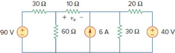
Use superposition to obtain vx in the circuit of Fig. 4.85. Check your result using PSpice or MultiSim.
Figure 4.85
Find the value of the voltage
Answer to Problem 17P
The value of the voltage
Explanation of Solution
Given data:
Refer to Figure 4.85 in the textbook.
Calculation:
In the given circuit, since there are three sources, let
Where
When
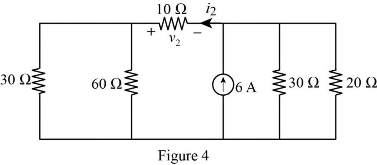
The given circuit is modified as shown in Figure 1.
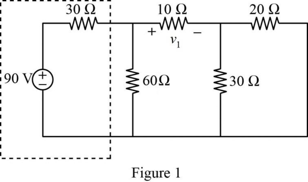
In Figure 1, the voltage source with series resistance is converted into current source with parallel resistance by source transformation method.
That is,
The source transformation is shown in Figure 2.
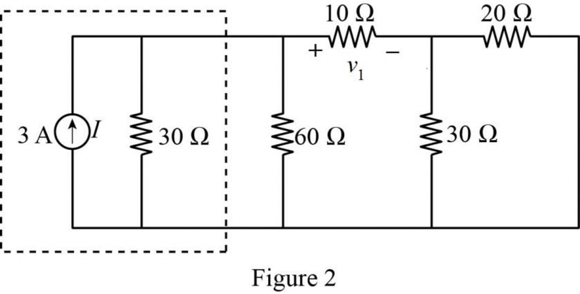
In Figure 2,
Similarly,
The modified Figure is shown in Figure 3.
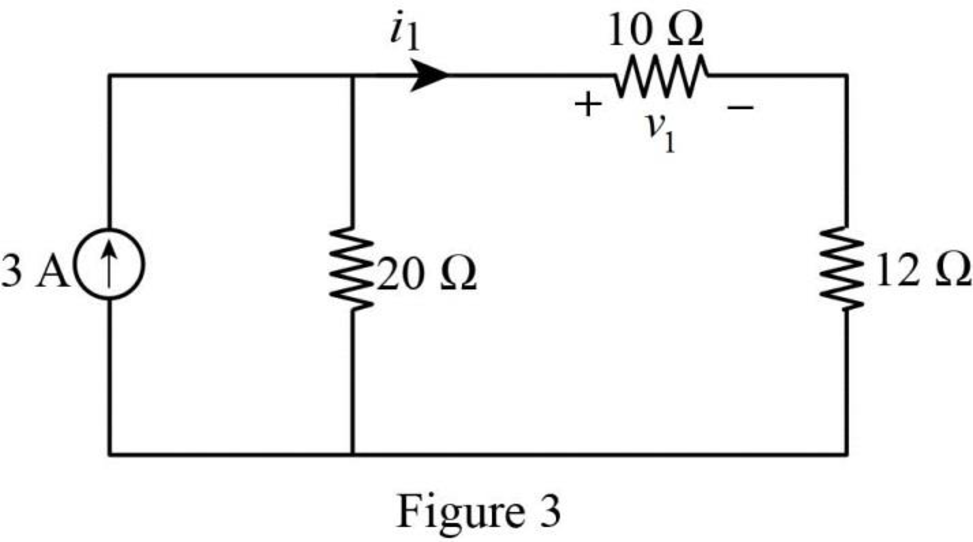
In Figure 3, the current
The voltage
Substitute
When
The given circuit is modified as shown in Figure 4.
In Figure 4,
Similarly,
The modified Figure is shown in Figure 5.
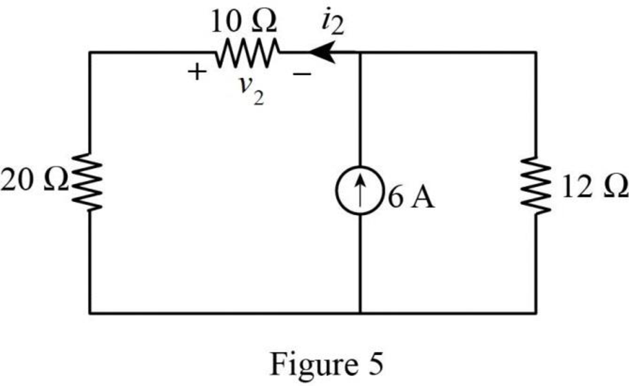
In Figure 5, the current
The voltage
Substitute
When
The given circuit is modified as shown in Figure 6.
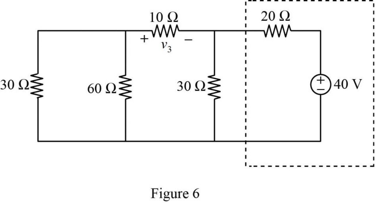
In Figure 6, the voltage source with series resistance is converted into current source with parallel resistance by source transformation method.
That is,
The source transformation is shown in Figure 7.
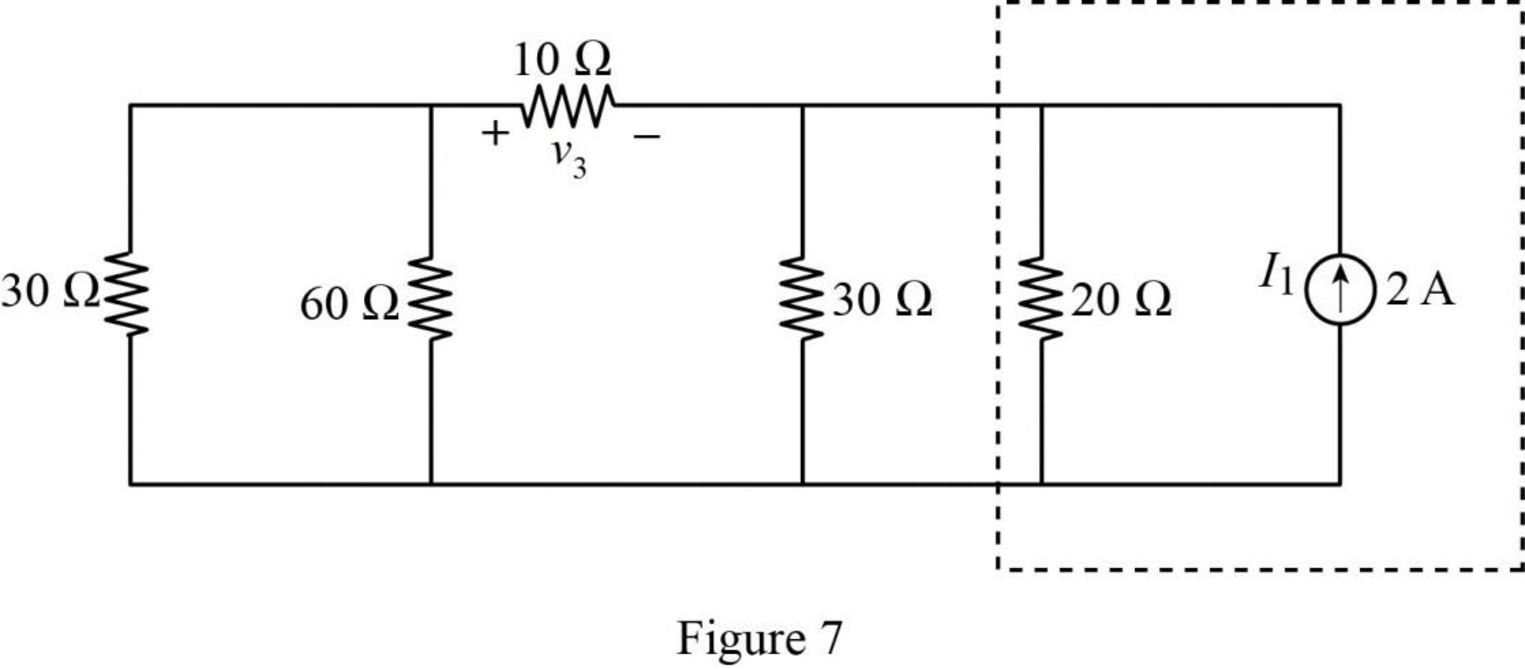
In Figure 7,
Similarly,
The modified Figure is shown in Figure 8.
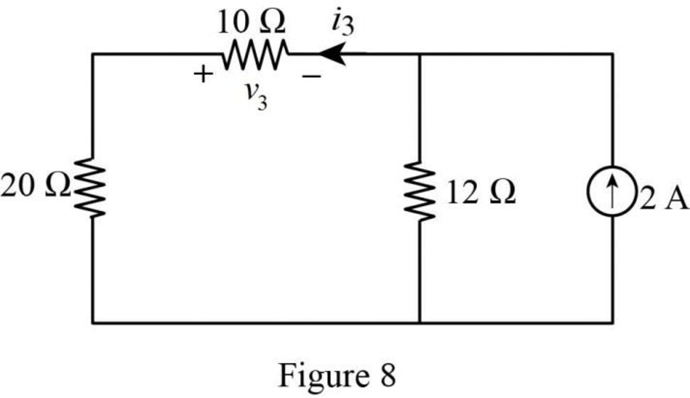
In Figure 8, the current
The voltage
Substitute
The total voltage
Substitute
PSPICE Simulation:
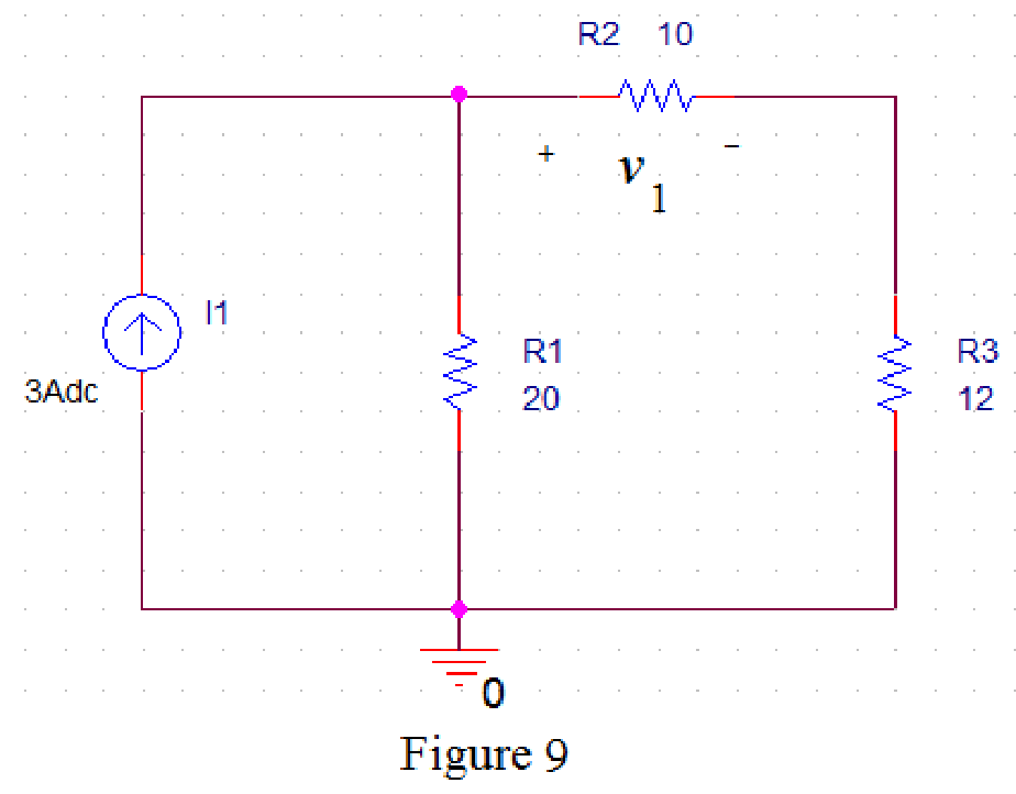
Refer to Figure 3, when
Draw the circuit diagram in PSPICE as shown in Figure 9.
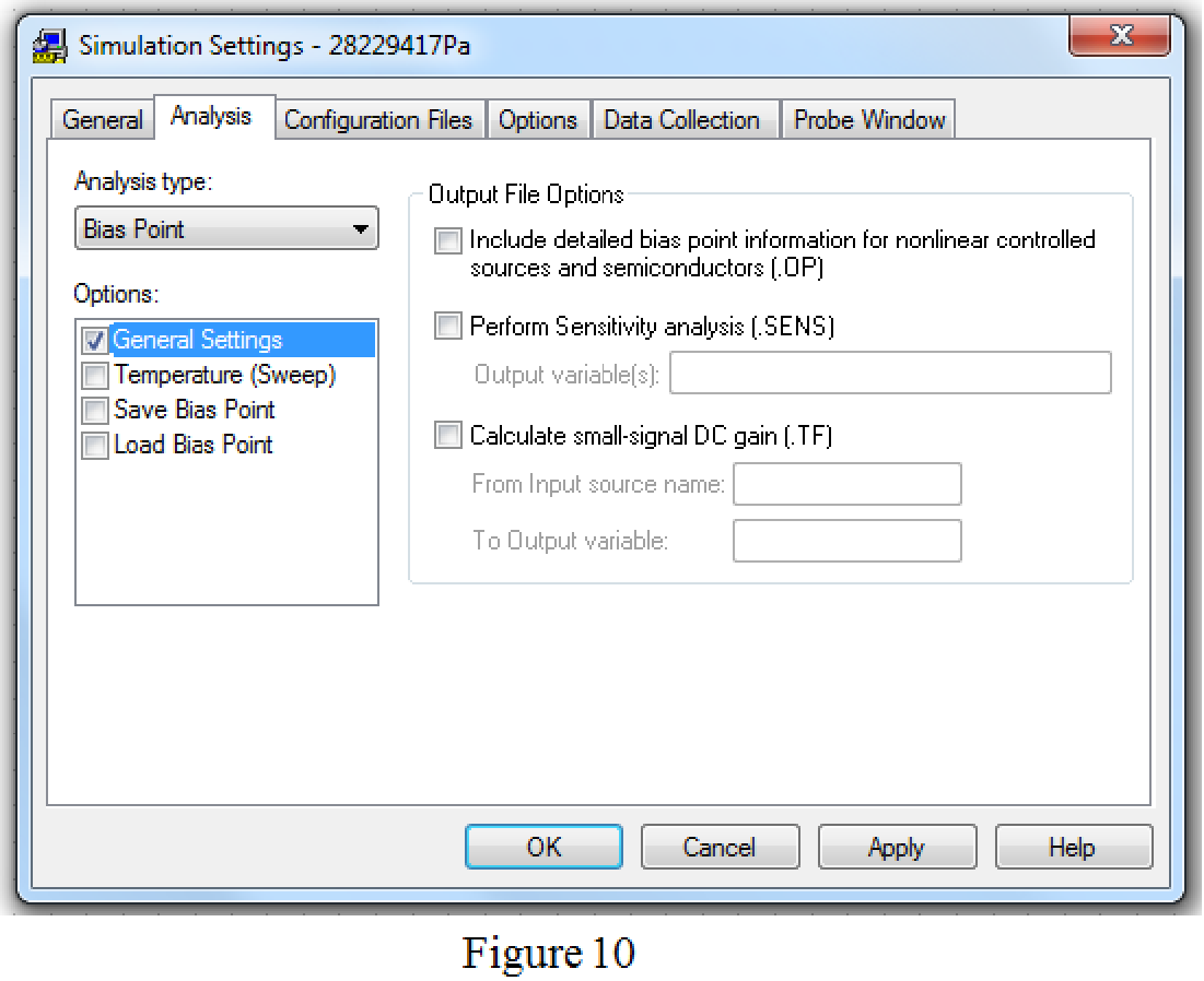
Save the circuit and provide the Simulation Settings as shown in Figure 10.
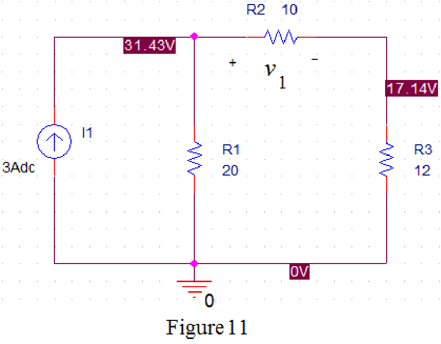
Now run the simulation and the results will be displayed as shown in Figure 11 by enabling “Enable Bias Voltage Display” icon.
Refer to Figure 5, when
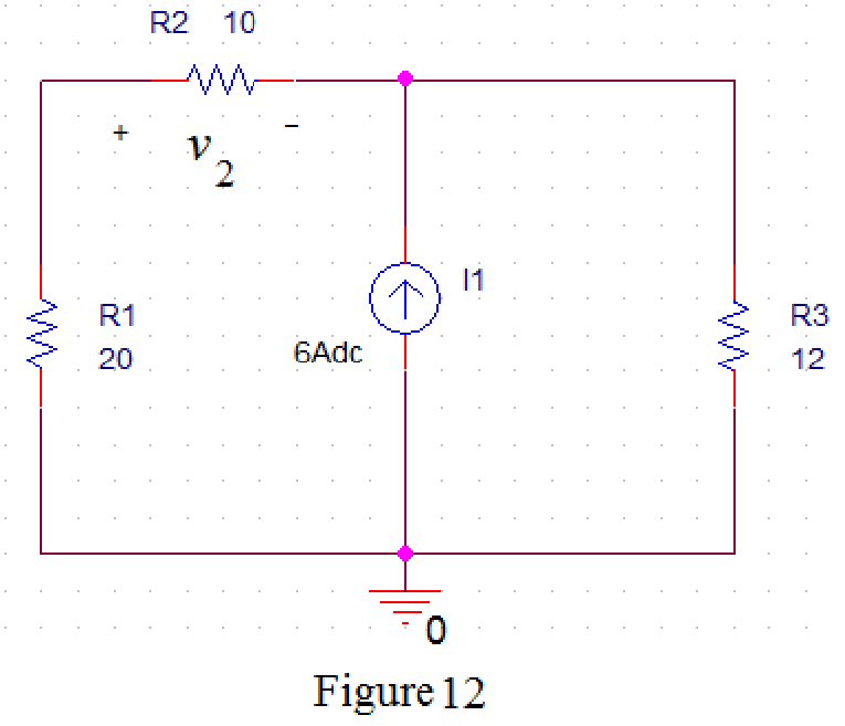
Draw the circuit diagram in PSPICE as shown in Figure 12.
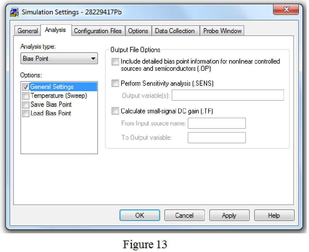
Save the circuit and provide the Simulation Settings as shown in Figure 13.
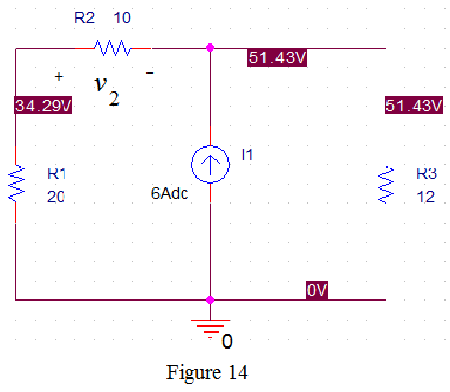
Now run the simulation and the results will be displayed as shown in Figure 14 by enabling “Enable Bias Voltage Display” icon.
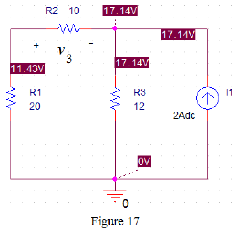
Refer to Figure 8, when
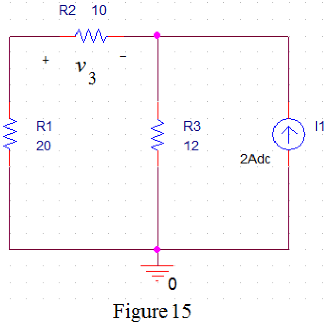
Draw the circuit diagram in PSPICE as shown in Figure 15.
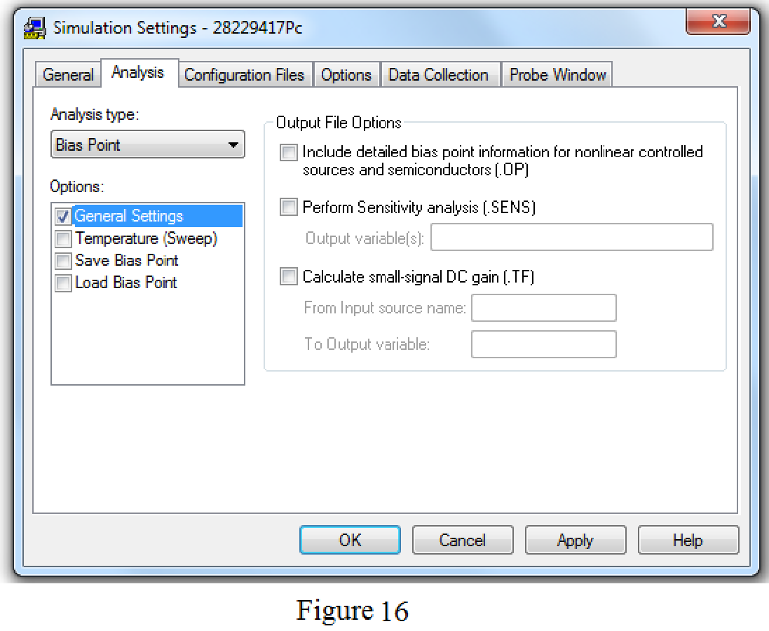
Save the circuit and provide the Simulation Settings as shown in Figure 16.
Now run the simulation and the results will be displayed as shown in Figure 17 by enabling “Enable Bias Voltage Display” icon.
From Figure 11, the voltage
From Figure 14, the voltage
From Figure 17, the voltage
Substitute
Conclusion:
Thus, the value of the voltage
Want to see more full solutions like this?
Chapter 4 Solutions
Fundamentals of Electric Circuits
Additional Engineering Textbook Solutions
Concepts Of Programming Languages
Problem Solving with C++ (10th Edition)
Mechanics of Materials (10th Edition)
Java How to Program, Early Objects (11th Edition) (Deitel: How to Program)
Fluid Mechanics: Fundamentals and Applications
Electric Circuits. (11th Edition)


- Phase (deg) Magnitude (dB) -20 -40 -60 -80 -100 ° -90 -180 -270 10-1 (i) ° Problem 5 Consider a unity (negative) feedback system with a proportional controller. The Bode plot of the plant transfer function G(s) is given as below. System: sys Frequency (rad/s): 1 Magnitude (dB): 13.9 System: sys Frequency (rad/s): 14.9 Magnitude (dB): 6.58 System: sys Frequency (rad/s): 1 Phase (deg): -9.76 10° System: sys Frequency (rad/s): 25.6 Magnitude (dB): -0.0703 System: sys Frequency (rad/s): 41.3 Magnitude (dB): -8.06 System: sys Frequency (rad/s): 200 Magnitude (dB): -44.4 System: sys Frequency (rad/s): 14.9 Phase (deg): -110 System: sys Frequency (rad/s): 25.6 Phase (deg): -148 System: sys Frequency (rad/s): 41.3 Phase (deg): -180 System: sys Frequency (rad/s): 200 Phase (deg): -247 101 Frequency (rad/s) 102 Find the gain crossover frequency, phase crossover frequency, gain margin and phase margin of the system. Is the closed-loop system stable? (ii) What is the steady-state error of the…arrow_forwardsolve and show in detail all calculationsarrow_forwardsolve and show in detail all calculationsarrow_forward
- solve and show in detail all calculationsarrow_forwardProblem 1 Consider the following system. In the figure, y(t) denotes the voltage across the capacitor. u(t) 1+ R W L + 0000 y(t) C Y(s) (i) Find the transfer function H(s): = of the system. U(s) Now suppose, R 10 KQ, L = 0.5 mH and C = 10 μF. (ii) Find the poles and zeros. Is the system BIBO stable? (iii) Compute settling time, rise time, peak time and % overshoot of the step response of the system. What the steady-state output for unit step input?arrow_forwardA 3-phase, 52 H.P, 50 Hz, 6-Pole, Y- connected induction motor runs at a speed of 980 rpm.The motor is supplied from 380 V mains and it takes a rated current of 80 A at 0.8 p.f. If the total stator losses are 1.7 kW, determine: the air-gap power, rotor copper loss, friction and windage losses?arrow_forward
- 12-3) PDF, mean, & variance A random variable has the PDF shown in the figure. a) Find the numerical value of the parameter K. b) Write the numerical expression for the PDF. c) Find the probability that the random variable is negative. d) Find the mean of x, the expected value of x², and the variance of x. K Px(x) 3 Xarrow_forwardPlease show all stepsarrow_forward12-4) Gaussian random variable A Gaussian random variable has a mean value of 4 and a standard deviation of 3. Find the probability that the value of the random variable exceeds 16. Repeat for the probability that it is less than -2. The discussion of Marcum's Q function given in the lecture notes may be helpful.arrow_forward
 Introductory Circuit Analysis (13th Edition)Electrical EngineeringISBN:9780133923605Author:Robert L. BoylestadPublisher:PEARSON
 Delmar's Standard Textbook Of ElectricityElectrical EngineeringISBN:9781337900348Author:Stephen L. HermanPublisher:Cengage Learning
 Programmable Logic ControllersElectrical EngineeringISBN:9780073373843Author:Frank D. PetruzellaPublisher:McGraw-Hill Education
 Fundamentals of Electric CircuitsElectrical EngineeringISBN:9780078028229Author:Charles K Alexander, Matthew SadikuPublisher:McGraw-Hill Education
 Electric Circuits. (11th Edition)Electrical EngineeringISBN:9780134746968Author:James W. Nilsson, Susan RiedelPublisher:PEARSON
 Engineering ElectromagneticsElectrical EngineeringISBN:9780078028151Author:Hayt, William H. (william Hart), Jr, BUCK, John A.Publisher:Mcgraw-hill Education,