
Concept explainers
Videos
Find the Thevenin equivalent at terminals a-b of the circuit in Fig. 4.107.
Figure 4.107
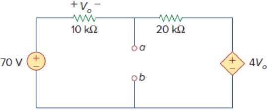
Find the Thevenin voltage and Thevenin resistance at terminals a-b of the circuit shown in Figure 4.107.
Answer to Problem 40P
The Thevenin voltage is
Explanation of Solution
Given data:
Refer to Figure 4.107 in the textbook.
The voltage source is
Calculation:
The given circuit is modified as shown in Figure 1.
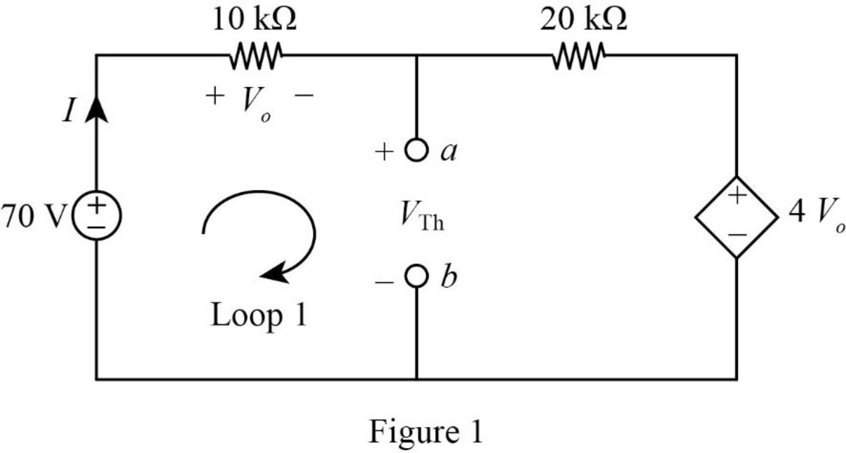
In Figure 1, apply Kirchhoff’s voltage law to the outer loop as follows,
In Figure 1, the voltage
Substitute equation (2) in equation (1),
Simplify the equation as follows,
In Figure 1, apply Kirchhoff’s voltage law to the Loop 1 as follows,
Substitute
In the given circuit, find the Thevenin resistance by turning off the
The modified circuit is shown in Figure 2.
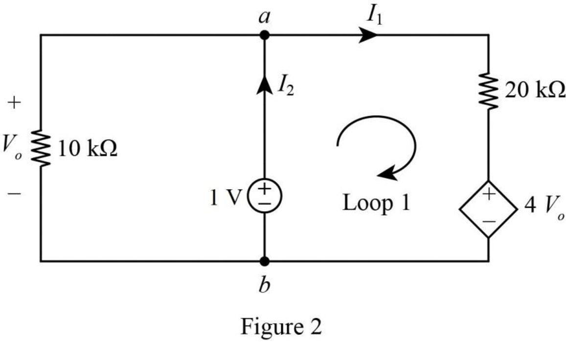
In Figure 2, apply Kirchhoff’s voltage law to the Loop 1 as follows,
In Figure 2, the voltage
Substitute
Simplify the equation as follows,
In Figure 2, the current
Substitute
Simplify the equation as follows,
In Figure 2, the Thevenin resistance is,
Substitute
Conclusion:
Thus, the Thevenin voltage is
Want to see more full solutions like this?
Chapter 4 Solutions
Fundamentals of Electric Circuits
Additional Engineering Textbook Solutions
Thermodynamics: An Engineering Approach
Elementary Surveying: An Introduction To Geomatics (15th Edition)
Electric Circuits. (11th Edition)
Starting Out with Programming Logic and Design (5th Edition) (What's New in Computer Science)
Starting Out With Visual Basic (8th Edition)
Java: An Introduction to Problem Solving and Programming (8th Edition)


- Please show all stepsarrow_forward12-4) Gaussian random variable A Gaussian random variable has a mean value of 4 and a standard deviation of 3. Find the probability that the value of the random variable exceeds 16. Repeat for the probability that it is less than -2. The discussion of Marcum's Q function given in the lecture notes may be helpful.arrow_forwardA transformer has a primary voltage of 240 V and a secondary voltage of 48 V. What is the turns ratio of this transformer?arrow_forward
- microprocers and microcontrolerarrow_forwardDesign a counter to count-up from 2 to 7 using three of D Flip Flops (3) 3-Bit Count up (3 to 5) Using D Flip-Flop: The State Equation of D Flip-Flop: Q(t+1)=D(t) => Dn=Qn Present State D Flip-Flop Next State n Q2p Q1p Q0p 3 0 1 1 1 Q2n Q1n Q0n D2 D1 D0 0 0 1 0 0 4 1 0 0 1 0 1 1 0 1 5 1 0 1 0 1 1 01 1 D2-Sum(3,4) and don't care X-Sum(0,1,2,6,7) D1=Sum(5) and don't care X=Sum(0,1,2,6,7) D0=Sum(4,5) and don't care X=Sum(0,1,2,6,7) Using K-map to simplify the functions: D2=Q1+Q0' D1=Q1'QO DO=Q1' XOX XOX Q2 10 Q2 01 Q2 1xx Q0 QO Qo D2 Q2 >CK Q2 D1 Q1 BCD CK Q1 DO QF ►CK Q0 ☐ Present State Next State D Flip-Flop n Q2p Q1p Q0p Q2n Q1n Q0n D2 D1 D0 2 0 1 0 0 1 1 0 1 1 3 0 1 1 1 0 0 1 00 4 1 0 0 1 0 1 1 0 1 5 1 0 1 1 1 0 1 1 0 6 1 1 0 0 1 0 0 1 0 D2 D2=Sum(3,4,5), X=Sum(0,1,7) D1 Q2 1 Q1 1 0 ☑ 0 Qo D2=Q0+Q1' ✗ 0 Q1arrow_forwardConsider the following 4×1 multiplexer with inputs: w0=2, w1=1, w2=x2' and w3=0 And with switches: S1 x1 and S0=x0 What is the multiplexer output f as a function of x2, x1 and x0?arrow_forward
- I need help adding a capacitor and a Zener diode to my circuit. I’m looking for a simple sketch or diagram showing how to connect them. i want diagram with final circuit after adding the zener diad and capacitor. don't do calclution or anything. thanksarrow_forwardQuestion 3 AC Motor Drives [15]Calculate the instantaneous currents delivered by the inverter if the direct axiscurrent required at a particular instant is 8.66A and the quadrature current is5A. Derive all equations for the three currents.arrow_forwardA certain signal f(t) has the following PSD (assume 12 load): Sp (w) = new + 8(w) - 1.5) + (w + 1.5)] (a) What is the mean power in the bandwidth w≤2 rad/see? (b) What is the mean power in the bandwidth -1.9 to 0.99 rad/sec? Paress(w) dw 2ㅈ -arrow_forward
- (75 Marks) JA signal (t) is bond 7)(t)(t) and f(t), are band-limited to 1.2 kHz each. These signals are to be limited to 9.6 kHz, and three other signals transmitted by means of time-division multiplexing. Set up scheme for accomplishing this multiplexing requirement, with each signal sampled at its Nyquist rate. What must be the speed of the commutator (the output but ram-k bit/sec)? the minimum band width? (25 Marks)arrow_forwardDraw the digital modulation outputs, ASK Amplitude Shift Keying) FSK (Frequency Shift Keying) and PSK (Phase Shift Keying). For baseband and carriet frequency as shown 101 wwwwwwwwwwww 010 BASESAND basband CARRIER Carralarrow_forwardplease show full working. I've included the solutionarrow_forward
 Introductory Circuit Analysis (13th Edition)Electrical EngineeringISBN:9780133923605Author:Robert L. BoylestadPublisher:PEARSON
 Delmar's Standard Textbook Of ElectricityElectrical EngineeringISBN:9781337900348Author:Stephen L. HermanPublisher:Cengage Learning
 Programmable Logic ControllersElectrical EngineeringISBN:9780073373843Author:Frank D. PetruzellaPublisher:McGraw-Hill Education
 Fundamentals of Electric CircuitsElectrical EngineeringISBN:9780078028229Author:Charles K Alexander, Matthew SadikuPublisher:McGraw-Hill Education
 Electric Circuits. (11th Edition)Electrical EngineeringISBN:9780134746968Author:James W. Nilsson, Susan RiedelPublisher:PEARSON
 Engineering ElectromagneticsElectrical EngineeringISBN:9780078028151Author:Hayt, William H. (william Hart), Jr, BUCK, John A.Publisher:Mcgraw-hill Education,