
Concept explainers
Videos
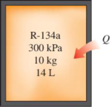
10 kg of R-134a at 300 kPa fills a rigid container whose volume is 14 L. Determine the temperature and total enthalpy in the container. The container is now heated until the pressure is 600 kPa. Determine the temperature and total enthalpy when the heating is completed.
FIGURE P3–42
The temperature and total enthalpy at initial and final states in the container.
The temperature and total enthalpy at initial and final states when the heating is completed.
Answer to Problem 42P
The temperature and total enthalpy at initial and final states in the container are
The temperature and total enthalpy at initial and final states when the heating is completed are are
Explanation of Solution
Since the process is a constant volume, calculate the specific volume.
Here, specific volume at states 1 and 2 are
The initial state represents the mixture, so temperature to be considered as the saturation temperature at given pressure.
Calculate the dryness fraction at state 1.
Here, specific volume at state 1 is
Calculate the specific enthalpy at state 1.
Here, specific enthalpy at saturated liquid is
Calculate the total enthalpy at state 1.
Here, mass of the refrigerant R-134a is m.
Similarly, calculate for
Here, dryness fraction at state 2 is
Calculate the specific enthalpy at state 2.
Calculate the total enthalpy at state 2.
Conclusion:
Substitute 14 L for
Write the formula of interpolation method of two variables.
Here, the variables denote by x and y are pressure and temperature.
Refer to Table A-12, obtain the values of below variables as in Table (I).
| Pressure, kPa | Temperature, |
| 280 | –1.25 |
| 300 | ? |
| 320 | 2.46 |
Substitute 280 for
Thus, the value obtained for saturation temperature at the given pressure is
Similarly, calculate the values of
Substitute
Substitute
Substitute 10 kg for m and 54.56 kJ/kg for
Thus, the temperature and total enthalpy at initial and final states in the container are
Similarly, calculate the values of
Repeat the above steps for
Thus, the temperature and total enthalpy at initial and final states in the container are
Want to see more full solutions like this?
Chapter 3 Solutions
Thermodynamics: An Engineering Approach
Additional Engineering Textbook Solutions
Automotive Technology: Principles, Diagnosis, And Service (6th Edition) (halderman Automotive Series)
Vector Mechanics for Engineers: Statics and Dynamics
Starting Out with Programming Logic and Design (5th Edition) (What's New in Computer Science)
Mechanics of Materials (10th Edition)
Modern Database Management
Java: An Introduction to Problem Solving and Programming (8th Edition)


- Determine the final pressure and temperature. The final pressure is kPa. The final temperature is ºC.arrow_forwardAir enters the 1-m2 inlet of an aircraft engine at 100 kPa and 20°C with a velocity of 184 m/s. Determine the volume flow rate, in m3/s, at the engine’s inlet and the mass flow rate, in kg/s, at the engine’s exit. The gas constant of air is R = 0.287 kPa·m3/kg·K. The volume flow rate at the engine’s inlet m3/s. The mass flow rate at the engine’s exit is kg/s.arrow_forwardThe ventilating fan of the bathroom of a building has a volume flow rate of 33 L/s and runs continuously. If the density of air inside is 1.20 kg/m3, determine the mass of air vented out in one day. The mass of air is kg.arrow_forward
- A steady-flow compressor is used to compress helium from 15 psia and 70°F at the inlet to 200 psia and 600°F at the outlet. The outlet area and velocity are 0.01 ft2 and 100 ft/s, respectively, and the inlet velocity is 53 ft/s. Determine the mass flow rate and the inlet area. The gas constant of helium is R = 2.6809 psia·ft3/lbm·R. The mass flow rate is lbm/s. The inlet area is ft2.arrow_forward1. The maximum and minimum stresses as well as the shear stress seen subjected the piece in plane A-A. Assume it is a cylinder with a diameter of 12.7mm 2. Draw the Mohr circle for the stress state using software. 3. Selection of the material for the prosthesis, which must be analyzed from the point of safety and cost view.arrow_forwardMarrow_forward
- × Your answer is incorrect. (Manometer) Determine the angle 0 of the inclined tube shown in figure below if the pressure at A is 1 psi greater than that at B. 1ft SG=0.61 十 A Ꮎ 1ft SG=1.0 8.8 ft 0 = Hi 15.20 deg Airarrow_forwardI don't know how to solve thisarrow_forward1. The maximum and minimum stresses as well as the shear stress seen subjected the piece in plane A-A. Assume it is a cylinder with a diameter of 12.7mm 2. Draw the Mohr circle for the stress state using software. 3. Selection of the material for the prosthesis, which must be analyzed from the point of safety and cost view.arrow_forward
- First, define the coordinate system XY with its origin at O2 and X-axis passing through O4 asshown above, then based on the provided steps Perform coordinate transformation from XY to xy to get the trajectory of point P. Show all the steps and calcualtionsarrow_forwardI don't know how to solve thisarrow_forwardQuestion 2 (40 Points) Consider the following double pendulum-like system with links ₁ and 12. The angles 0 and & could have angular velocities ėêk and êk, respectively, where ②k is a unit vector that points out of the page and is perpendicular to x and y. They could also have angular accelerations Ök and êk. The angle is defined relative to the angle 0. The link 12 is a spring and can extend or compress at a rate of 12. It can also have a rate of extension or compression Ï2. li y êr1 êe 12 χ 3 еф er2 ده لج 1) Express the velocity of the mass in terms of the unit vectors ê0, êr1, êø, and êr2, and any extension/contraction of the links (e.g.,. i; and Ï¿) (12 Points) 2) Express the acceleration of the mass in terms of the unit vectors ê¤, ê×1, êp, and êÃ2, and any extension/contraction of the links (e.g.,. İ; and Ï¿) (12 Points) 3) Express the velocity of the mass in terms of unit vectors î and ĵ that point in the x and y directions, respectively. Also include the appropriate,…arrow_forward
 Elements Of ElectromagneticsMechanical EngineeringISBN:9780190698614Author:Sadiku, Matthew N. O.Publisher:Oxford University Press
 Mechanics of Materials (10th Edition)Mechanical EngineeringISBN:9780134319650Author:Russell C. HibbelerPublisher:PEARSON
 Thermodynamics: An Engineering ApproachMechanical EngineeringISBN:9781259822674Author:Yunus A. Cengel Dr., Michael A. BolesPublisher:McGraw-Hill Education
 Control Systems EngineeringMechanical EngineeringISBN:9781118170519Author:Norman S. NisePublisher:WILEY
 Mechanics of Materials (MindTap Course List)Mechanical EngineeringISBN:9781337093347Author:Barry J. Goodno, James M. GerePublisher:Cengage Learning
 Engineering Mechanics: StaticsMechanical EngineeringISBN:9781118807330Author:James L. Meriam, L. G. Kraige, J. N. BoltonPublisher:WILEY