Videos
Problems 7 through 10 deal with the RC circuit in Fig. 3.7.8, containing a resistor (R ohms), a capacitor (C farads), a switch, a source of emf, but no inductor Substitution of
for the charge
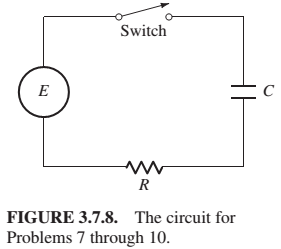
Suppose that in the circuit of Fig. 3.7.8, we have
Want to see the full answer?
Check out a sample textbook solution
Chapter 3 Solutions
Differential Equations: Computing and Modeling (5th Edition), Edwards, Penney & Calvis
Additional Engineering Textbook Solutions
Introduction To Programming Using Visual Basic (11th Edition)
Modern Database Management
SURVEY OF OPERATING SYSTEMS
Management Information Systems: Managing The Digital Firm (16th Edition)
Elementary Surveying: An Introduction To Geomatics (15th Edition)
Starting Out With Visual Basic (8th Edition)


- Activity Time (days) Predecessors Earliest Expected Completion Time (TE) Latest Expected Completion Time (TE) 1 4 2 5 1 3456782222 6 1 7 1 4 4 6 2,3 5 3 5 5,7 9 4 7 10 3 6,9 11 5 8,9,10 12 4 11 Slack Critical Path? Yes or Noarrow_forwardI would like to know about the following concepts: 1. defragmentation 2. disk management 3. hardware RAIDarrow_forwardNode.js, Express, and Nunjucks Templates?arrow_forward
- CIT244 Program Project 3 Assignment As with any assigned program, do not wait until the last minute to start. Start early in the week the program is due so you can ask questions if you get stuck Node.js and Express and Nunjucks Templates We have gotten to the good stuff. There is a program similar to this assignment given as the last example in the lecture notes for the week that discusses node static files. This program will take more time that previous assignments. There are several examples you should study first, particularly the pizza order example program available in the examples programs folder for the week discussing static files. You should study and run the pizza order program before trying this program. The pseudo-company is called Sun or Fun, which offers cheap flights from Louisville to either Miami or Vegas. Here's a video of how it should work. NOTE: You will hear or see references to Handlebars in this video. We used to use Handlebars, but it will be Nunjucks that we…arrow_forwardhow to write the expression for the outputarrow_forwardPlease answer the exercise below(C programme)arrow_forward
- I need to list and know about some local storage options available in Windows Server 2019, thank youarrow_forwardPlease answer both Exercise 1 and2(these questions are not GRADED)arrow_forwardDiscussion 1. Comment on your results. 2. Compare between the practical and theoretical results. 3. Find VB, Vc on the figure below: 3V V₁₁ R₁ B IR, R, IR, R www ΙΚΩ www www I 1.5KQ 18₁ 82002 R₁ 3.3KQ R₂ 2.2KQ E Darrow_forward
- Agile1. a. Describe it and how it differs from other SDLC approachesb. List and describe the two primary terms for the agile processc. What are the three activities in the Construction phasearrow_forwardhow are youarrow_forwardneed help with thi Next, you are going to combine everything you've learned about HTML and CSS to make a static site portfolio piece. The page should first introduce yourself. The content is up to you, but should include a variety of HTML elements, not just text. This should be followed by an online (HTML-ified) version of your CV (Resume). The following is a minimum list of requirements you should have across all your content: Both pages should start with a CSS reset (imported into your CSS, not included in your HTML) Semantic use of HTML5 sectioning elements for page structure A variety other semantic HTML elements Meaningful use of Grid, Flexbox and the Box Model as appropriate for different layout components A table An image Good use of CSS Custom Properties (variables) Non-trivial use of CSS animation Use of pseudeo elements An accessible colour palette Use of media queries The focus of this course is development, not design. However, being able to replicate a provided design…arrow_forward
 C++ for Engineers and ScientistsComputer ScienceISBN:9781133187844Author:Bronson, Gary J.Publisher:Course Technology Ptr
 Operations Research : Applications and AlgorithmsComputer ScienceISBN:9780534380588Author:Wayne L. WinstonPublisher:Brooks Cole
 Systems ArchitectureComputer ScienceISBN:9781305080195Author:Stephen D. BurdPublisher:Cengage Learning
 Principles of Information Systems (MindTap Course...Computer ScienceISBN:9781285867168Author:Ralph Stair, George ReynoldsPublisher:Cengage Learning