Videos
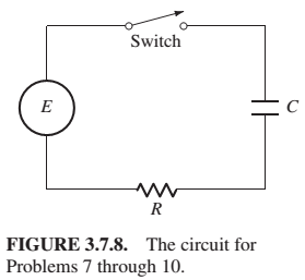
Problems 7 through 10 deal with the RC circuit in Fig. 3.7.8, containing a resistor (R ohms), a capacitor (C farads), a switch, a source of emf, but no inductor Substitution of
for the charge
An emf of voltage
Want to see the full answer?
Check out a sample textbook solution
Chapter 3 Solutions
Differential Equations: Computing and Modeling (5th Edition), Edwards, Penney & Calvis
Additional Engineering Textbook Solutions
Management Information Systems: Managing The Digital Firm (16th Edition)
Computer Science: An Overview (13th Edition) (What's New in Computer Science)
Starting Out With Visual Basic (8th Edition)
Elementary Surveying: An Introduction To Geomatics (15th Edition)
Database Concepts (8th Edition)


- I need help to resolve or draw the diagrams. thank youarrow_forwardYou were requested to design IP addresses for the following network using the addressblock 166.118.10.0/8, connected to Internet with interface 168.118.40.17 served by the serviceprovider with router 168.118.40.1/20.a) Specify an address and net mask for each network and router interface in the table provided. b) Give the routing table at Router 1.c) How will Router 1 route the packets with destinationi) 168.118.10.5ii) 168.118.10.103iii) 168.119.10.31iii) 168.118.10.153arrow_forwardI would like to get help to draw an object relationship diagram for a typical library system.arrow_forward
- Given the network of bridges in figure, and assuming that LAN ports on A, B, C, D, E, J are 10 Mbs (cost 100 for ports) except for ports on F, G, I, H, K which are 100Mbps LANs (cost 19 for ports) Draw the obtained spanning tree, cross the blocking state ports, and circle the designated ports and write the best cost broadcasted by each router next to its root port. list in logic level detail the expected last STP messages that will define the final status at each router.arrow_forwardNext, you are going to combine everything you've learned about HTML and CSS to make a static site portfolio piece. The page should first introduce yourself. The content is up to you, but should include a variety of HTML elements, not just text. This should be followed by an online (HTML-ified) version of your CV (Resume). The following is a minimum list of requirements you should have across all your content: Both pages should start with a CSS reset (imported into your CSS, not included in your HTML) Semantic use of HTML5 sectioning elements for page structure A variety other semantic HTML elements Meaningful use of Grid, Flexbox and the Box Model as appropriate for different layout components A table An image Good use of CSS Custom Properties (variables) Non-trivial use of CSS animation Use of pseudeo elements An accessible colour palette Use of media queries The focus of this course is development, not design. However, being able to replicate a provided design for the web is…arrow_forwardI would like to get help to draw an object relationship diagram for a typical library system.arrow_forward
- https://docs.google.com/document/d/1lk0DgaWfVezagyjAEskyPoe9Ciw3J2XUH_HQfnWSmwU/edit?usp=sharing using the link for the case study answer the below questionarrow_forwardFinally, your going to write several small javascript functions to practice with javascript core programming (basically just using javascript as a normal scripting language). For each section you can hardcode input values, and all output should go to console (we'll worry about the actual web page on Assignment 4). You can complete these all in one HTML file, or create one file for each part.arrow_forwardWrite a C program to calculate the checksum for a given line of an IntelHex file. To get full points, you must be able to explain to the instructor the individual parts of the IntelHex line (see below), as well as any part of your code. Definition:The checksum is calculated as the two's complement of the sum of the individual bytes from the beginning of the line to the checksum. Example:If you enter this string: :10010000214601360121470136007EFE09D21901XX You should get a checksum of 40 instead of XX. Demonstrate the completion of the task by calculating checksums, for example, for the following strings: :100010000C9445000C9445000C9445000C944500xx:100020000C9445000C9445000C9445000C944500xx:100030000C9445000C9445000C9445000C944500xx:100040000C9445000C9445000C9445000C944500xxarrow_forward
- Write a program to calculate the function sin(x) or cos(x) using a Taylor series expansion around the point 0. In other words, you will program the sine or cosine function yourself, without using any existing solution. You can enter the angles in degrees or radians. The program must work for any input, e.g. -4500° or +8649°. The function will have two arguments: float sinus(float radians, float epsilon); For your own implementation, use one of the following relations (you only need to program either sine or cosine, you don't need both): Tip 1: Of course, you cannot calculate the sum of an infinite series indefinitely. You can see (if not, look in the program) that the terms keep getting smaller, so there will definitely be a situation where adding another term will not change the result in any way (see problem 1.3 – machine epsilon). However, you can end the calculation even earlier – when the result changes by less than epsilon (a pre-specified, sufficiently small number, e.g.…arrow_forwardWrite a C program that finds and prints the machine epsilon for the float and double data types. Also print the values of __FLT_EPSILON__ and __DBL_EPSILON__ defined in float.h. Reminder – the phrase data type tells how the compiler “understands” the ones and zeros you are working with. This identifies whether you are working with integers, letters, real numbers, and so on. Another definition:Machine epsilon is the "distance" between the number 1 and its immediate right neighbor. We work in binary (decimal is in parentheses): 1 + 0,1 = 1,1 (1 + 1/2 = 1,5) 1 + 0,01 = 1,01 (1 + 1/4 = 1,25) 1 + 0,001 = 1,001 (1 + 1/8 = 1,125) then, due to the limited accuracy of the computer at a certain number of decimal places, a situation arises where 1 + 0.0…001 = 1 (instead of the correct 1.0…001). Then the previous number 0.0…01 is called the machine epsilon . It is obvious that its value may be different on different computers. However, the machine…arrow_forwardWrite a program that performs a rotational bit shift to the right for a positive integer. The user enters a number, the number of bits to shift (and, if you want, the direction of the shift, but right is enough). Example:The number 9 (in binary form 1001) when rotated to the right by 1 bit becomes 1100. Tip : A bit rotation (also known as a cyclic shift) is an operation in which the bits in a binary number are shifted a certain number of places to the right or left, with bits that “fall out” at one end being returned to the opposite end. So, start with a bit shift operation. Write a few examples on paper before programming.Tip : Use the unsigned int data type.You can get the number of bits of this data type as follows: int bit_count = sizeof (unsigned int ) * 8arrow_forward
 C++ for Engineers and ScientistsComputer ScienceISBN:9781133187844Author:Bronson, Gary J.Publisher:Course Technology Ptr
 Operations Research : Applications and AlgorithmsComputer ScienceISBN:9780534380588Author:Wayne L. WinstonPublisher:Brooks Cole
 Systems ArchitectureComputer ScienceISBN:9781305080195Author:Stephen D. BurdPublisher:Cengage Learning
 Principles of Information Systems (MindTap Course...Computer ScienceISBN:9781285867168Author:Ralph Stair, George ReynoldsPublisher:Cengage Learning