
INTERNATIONAL EDITION---Engineering Mechanics: Statics, 14th edition (SI unit)
14th Edition
ISBN: 9780133918922
Author: Russell C. Hibbeler
Publisher: PEARSON
expand_more
expand_more
format_list_bulleted
Concept explainers
Videos
Textbook Question
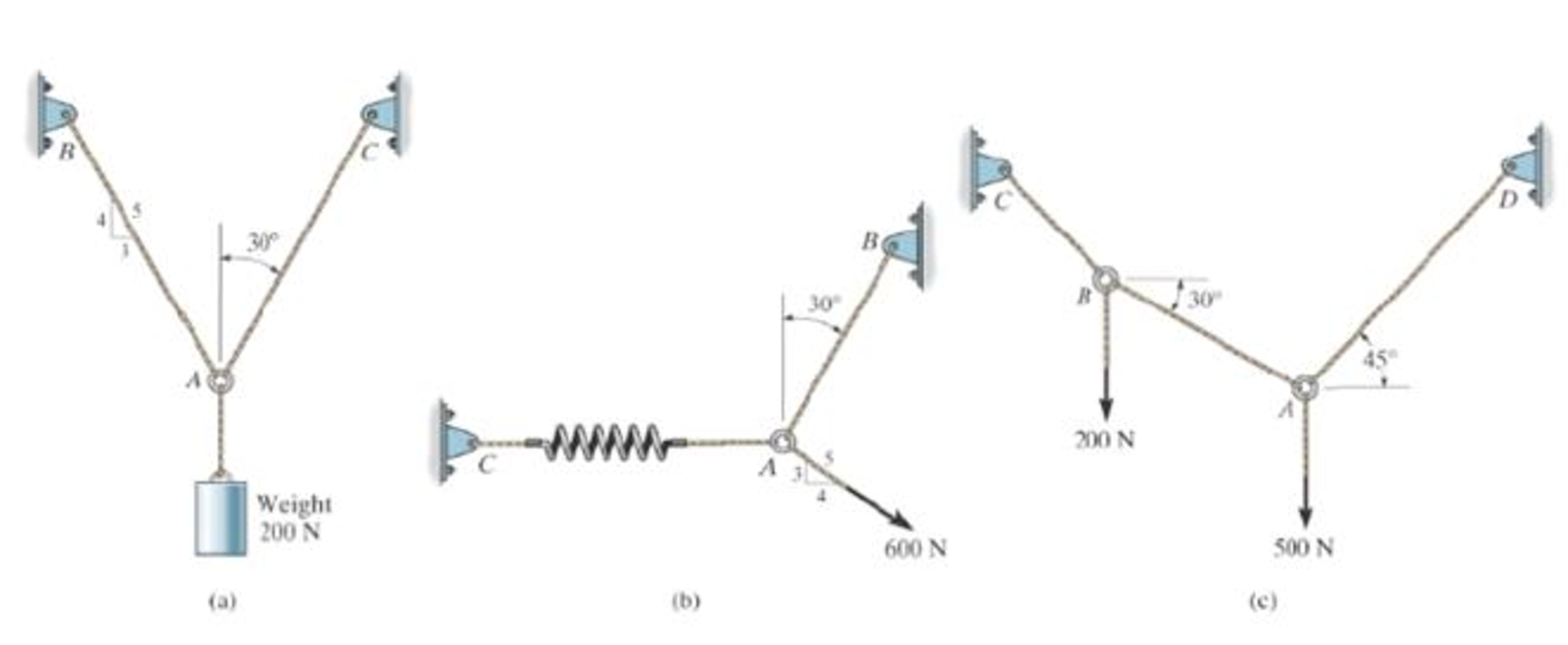
Chapter 3.3, Problem 1PP
In each case, draw a free-body diagram of the ring at A and identify each force.
Expert Solution & Answer

Learn your wayIncludes step-by-step video

schedule08:52
Students have asked these similar questions
Example
-4s
F(s) =
=
(s²+4)²
As + B Cs+D
+
(s²+4) (s²+4)²
(s²+4)
(H.W)
Q1/ Find L[t et sin t]
Q2/ Find The Laplace Transform
f(t) = [sint
[sint 0
b) The 50 mm diameter rod is placed in a hole, lubricated walls. There is no clearance
between the rod and the sides of the hole. Determine the change in length of the rod if
an 8 kN load is applied. Take E(brass) = 80 GPa; v = 0.55
[10]
50 mmm
300 rat
3
Chapter 3 Solutions
INTERNATIONAL EDITION---Engineering Mechanics: Statics, 14th edition (SI unit)
Ch. 3.3 - In each case, draw a free-body diagram of the ring...Ch. 3.3 - Do not solve.Ch. 3.3 - Determine the force in each supporting cable.Ch. 3.3 - Determine the shortest cable ABC that can be used...Ch. 3.3 - Neglect the size of the pulley.Ch. 3.3 - Determine the unstretched length of the spring.Ch. 3.3 - If the mass of cylinder C is 40 kg, determine the...Ch. 3.3 - Also, find the angle .Ch. 3.3 - Determine the magnitudes of F1 and F2 for...Ch. 3.3 - Determine the magnitude of F1 and its angle for...
Ch. 3.3 - Determine the magnitude and direction of F so...Ch. 3.3 - The bottom one is subjected to a 125-N force at...Ch. 3.3 - If the forces are concurrent at point O, determine...Ch. 3.3 - Determine the tension force in member C and its...Ch. 3.3 - If the tension in AB is 60 lb, determine the...Ch. 3.3 - The cords ABC and BD can each support a maximum...Ch. 3.3 - Determine the maximum force F that can be...Ch. 3.3 - Determine the angle for equilibrium and the force...Ch. 3.3 - Prob. 11PCh. 3.3 - Determine the force in each of the cables AB and...Ch. 3.3 - Prob. 13PCh. 3.3 - The springs are shown in the equilibrium position.Ch. 3.3 - If the block is held in the equilibrium position...Ch. 3.3 - Note that s = 0 when the cylinders are removed.Ch. 3.3 - Prob. 17PCh. 3.3 - determine the stiffness of the spring to hold the...Ch. 3.3 - Take k = 180 N/m.Ch. 3.3 - If the spring has an unstretched length of 2 ft,...Ch. 3.3 - Cord AB is 2 ft long. Take k = 50 lb/ft.Ch. 3.3 - Determine the horizontal force F applied to the...Ch. 3.3 - Determine the displacement d of the cord from the...Ch. 3.3 - Determine the distances x and y for equilibrium if...Ch. 3.3 - Determine the magnitude of F1 and the distance y...Ch. 3.3 - Determine the force in each cord for equilibrium.Ch. 3.3 - Determine the largest mass of pipe that can be...Ch. 3.3 - If each light has a weight of 50 lb. determine the...Ch. 3.3 - Determine the tension developed in each cord...Ch. 3.3 - Determine the maximum mass of the lamp that the...Ch. 3.3 - If x = 2 m determine the force F and the sag s for...Ch. 3.3 - If F = 80 N. determine the sag s and distance x...Ch. 3.3 - Determine the tension in each cord and the angle ...Ch. 3.3 - Determine the largest weight of the lamp that can...Ch. 3.3 - Also, what is the force in cord AB? Hint: use the...Ch. 3.3 - Determine the position x and the tension developed...Ch. 3.3 - Prob. 37PCh. 3.3 - Take F = 300 N and d = 1 m.Ch. 3.3 - If a force of F = 100 N is applied horizontally to...Ch. 3.3 - If the cable can be attached at either points A...Ch. 3.3 - Determine the position x and the tension in the...Ch. 3.3 - The cord is fixed to a pin at A and passes over...Ch. 3.3 - Establish appropriate dimensions and use an...Ch. 3.3 - If the maximum tension that can be supported by...Ch. 3.3 - If the angle between AB and BC is 30, determine...Ch. 3.3 - If the distance BC is 1.5 m, and AB can support a...Ch. 3.4 - Determine the magnitude of forces F1, F2, F3, so...Ch. 3.4 - Determine the tension developed in cables AB, AC,...Ch. 3.4 - Determine the tension developed in cables AB, AC,...Ch. 3.4 - F310. Determine the tension developed in cables...Ch. 3.4 - Determine the tension in these wires.Ch. 3.4 - Determine the force developed in each cable for...Ch. 3.4 - Determine the magnitudes of F1, F2, and F3 for...Ch. 3.4 - If the bucket and its contents have a total weight...Ch. 3.4 - Each spring has on unstretched length of 2 m and a...Ch. 3.4 - Determine the force in each cable needed to...Ch. 3.4 - Determine the tension in the cables in order to...Ch. 3.4 - Determine the maximum mass of the crate so that...Ch. 3.4 - Determine the force in each cable if F = 500 lb.Ch. 3.4 - Determine the greatest force F that can be applied...Ch. 3.4 - Determine the tens on developed in cables AB and...Ch. 3.4 - Also, what is the force developed along strut AD?Ch. 3.4 - Determine the tension developed in each cable for...Ch. 3.4 - Determine the maximum weight of the crate that can...Ch. 3.4 - Prob. 56PCh. 3.4 - If each cord can sustain a maximum tension of 50 N...Ch. 3.4 - which has a mass of 15 kg. Take h = 4 m.Ch. 3.4 - Take h = 3.5 m.Ch. 3.4 - Determine the force in each chain for equilibrium....Ch. 3.4 - Determine the tension in each cable for...Ch. 3.4 - If the maximum force in each rod con not exceed...Ch. 3.4 - Determine the tension developed in each cable for...Ch. 3.4 - If cable AD is tightened by a turnbuckle and...Ch. 3.4 - If cable AD is tightened by a turnbuckle and...Ch. 3.4 - Determine the tension developed in cables AB, AC,...Ch. 3.4 - Determine the maximum weight of the crate so that...Ch. 3.4 - If the bolt exerts a force of 50 lb on the pipe in...Ch. 3.4 - Prob. 2RPCh. 3.4 - Determine the maximum weight of the flowerpot that...Ch. 3.4 - Determine the magnitude of the applied vertical...Ch. 3.4 - Prob. 5RPCh. 3.4 - Determine the magnitudes of F1, F2, and F3 for...Ch. 3.4 - Determine the force in each cable needed to...Ch. 3.4 - If cable AB is subjected to a tension of 700 N,...
Additional Engineering Textbook Solutions
Find more solutions based on key concepts
Summarize the distinction between a machine language and an assembly language.
Computer Science: An Overview (13th Edition) (What's New in Computer Science)
Write the declaration for two variables called miles and flowRate. Declare the variable miles to be of type int...
Java: An Introduction to Problem Solving and Programming (8th Edition)
What is the disadvantage of having too many features in a language?
Concepts Of Programming Languages
The beam AB is pin supported at A and supported by a cable BC. A separate cable CG is used to hold up the frame...
Mechanics of Materials (10th Edition)
The current source in the circuit shown generates the current pulse
Find (a) v (0); (b) the instant of time gr...
Electric Circuits. (11th Edition)
Why should you avoid making class members protected when possible?
Starting Out with Java: From Control Structures through Objects (7th Edition) (What's New in Computer Science)
Knowledge Booster


Learn more about
Need a deep-dive on the concept behind this application? Look no further. Learn more about this topic, mechanical-engineering and related others by exploring similar questions and additional content below.Similar questions
- The Mach number NM for flow of a perfect gas in a pipe depends upon the specific-heat ratio k (dimensionless), the pressure p, the density ρ, and the velocity V. Obtain by dimensional reasoning the form of the Mach number expression. (Buckingham pi)Answer: NM = f(V/sqrt(p/ρ), k)arrow_forwardoyfr 3. The figure shows a frame under the influence of an external loading made up of five forces and two moments. Use the scalar method to calculate moments. a. Write the resultant force of the external loading in Cartesian vector form. b. Determine the & direction of the resultant moment of the external loading about A. 15 cm 18 cm 2.2 N-m B 50 N 45° 10 cm 48 N.m 250 N 60 N 20 21 50 N 25 cm 100 N A 118, 27cm 5, 4:1arrow_forwardAssume the Link AO is the input and revolves 360°, determine a. the coordinates of limit positions of point B, b. the angles (AOC) corresponding to the limit positionsarrow_forward
- oyfr 3. The figure shows a frame under the influence of an external loading made up of five forces and two moments. Use the scalar method to calculate moments. a. Write the resultant force of the external loading in Cartesian vector form. b. Determine the & direction of the resultant moment of the external loading about A. 15 cm 18 cm 2.2 N-m B 50 N 45° 10 cm 48 N.m 250 N 60 N 20 21 50 N 25 cm 100 N A 118, 27cm 5, 4:1arrow_forwardThe 2-mass system shown below depicts a disk which rotates about its center and has rotational moment of inertia Jo and radius r. The angular displacement of the disk is given by 0. The spring with constant k₂ is attached to the disk at a distance from the center. The mass m has linear displacement & and is subject to an external force u. When the system is at equilibrium, the spring forces due to k₁ and k₂ are zero. Neglect gravity and aerodynamic drag in this problem. You may assume the small angle approximation which implies (i) that the springs and dampers remain in their horizontal / vertical configurations and (ii) that the linear displacement d of a point on the edge of the disk can be approximated by d≈re. Ө K2 www m 4 Cz 777777 Jo Make the following assumptions when analyzing the forces and torques: тв 2 0>0, 0>0, x> > 0, >0 Derive the differential equations of motion for this dynamic system. Start by sketching LARGE and carefully drawn free-body-diagrams for the disk and the…arrow_forwardA linear system is one that satisfies the principle of superposition. In other words, if an input u₁ yields the output y₁, and an input u2 yields the output y2, the system is said to be linear if a com- bination of the inputs u = u₁ + u2 yield the sum of the outputs y = y1 + y2. Using this fact, determine the output y(t) of the following linear system: given the input: P(s) = = Y(s) U(s) = s+1 s+10 u(t) = e−2+ sin(t) =earrow_forward
- The manometer fluid in the figure given below is mercury where D = 3 in and h = 1 in. Estimate the volume flow in the tube (ft3/s) if the flowing fluid is gasoline at 20°C and 1 atm. The density of mercury and gasoline are 26.34 slug/ft3 and 1.32 slug/ft3 respectively. The gravitational force is 32.2 ft/s2.arrow_forwardUsing the Bernoulli equation to find the general solution. If an initial condition is given, find the particular solution. y' + xy = xy¯¹, y(0) = 3arrow_forwardTest for exactness. If exact, solve. If not, use an integrating factor as given or obtained by inspection or by the theorems in the text. a. 2xydx+x²dy = 0 b. (x2+y2)dx-2xydy = 0 c. 6xydx+5(y + x2)dy = 0arrow_forward
- Newton's law of cooling. A thermometer, reading 5°C, is brought into a room whose temperature is 22°C. One minute later the thermometer reading is 12°C. How long does it take until the reading is practically 22°C, say, 21.9°C?arrow_forwardSolve a. y' + 2xy = ex-x² b. y' + y sin x = ecosx, y(0) = −1 y(0) = −2.5arrow_forward= MMB 241 Tutorial 3.pdf 2/6 90% + + 5. The boat is traveling along the circular path with a speed of v = (0.0625t²) m/s, where t is in seconds. Determine the magnitude of its acceleration when t = 10 s. 40 m v = 0.0625² 6. If the motorcycle has a deceleration of at = (0.001s) m/s² and its speed at position A is 25 m/s, determine the magnitude of its acceleration when it passes point B. .A 90° 300 m n B 2arrow_forward
arrow_back_ios
SEE MORE QUESTIONS
arrow_forward_ios
Recommended textbooks for you
 International Edition---engineering Mechanics: St...Mechanical EngineeringISBN:9781305501607Author:Andrew Pytel And Jaan KiusalaasPublisher:CENGAGE L
International Edition---engineering Mechanics: St...
Mechanical Engineering
ISBN:9781305501607
Author:Andrew Pytel And Jaan Kiusalaas
Publisher:CENGAGE L
Ch 2 - 2.2.2 Forced Undamped Oscillation; Author: Benjamin Drew;https://www.youtube.com/watch?v=6Tb7Rx-bCWE;License: Standard youtube license