
Physics for Scientists and Engineers, Technology Update (No access codes included)
9th Edition
ISBN: 9781305116399
Author: Raymond A. Serway, John W. Jewett
Publisher: Cengage Learning
expand_more
expand_more
format_list_bulleted
Videos
Textbook Question
Chapter 32, Problem 32.24P
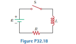
Consider the circuit in Figure P32.18, taking ε = 6.00 V, L = 8.00 mH, and R = 4.00 Ω. (a) What is the inductive time constant of the circuit? (b) Calculate the current in the circuit 250 μs after the switch is closed. (c) What is the value of the final steady-state current? (d) After what time interval does the current reach 80.0% of its maximum value?
Expert Solution & Answer

Trending nowThis is a popular solution!

Students have asked these similar questions
As I carry a box up a flight of stairs, am I doing positive work or negative work on the box? Provide a mathematical explanation.
As a ball falls under the influence of gravity, does gravity do positive work or negative work? Provide a mathematical explanation.
Under what circumstances is it bad to describe kinetic energy as k = 1/2mv^2
Chapter 32 Solutions
Physics for Scientists and Engineers, Technology Update (No access codes included)
Ch. 32 - A coil with zero resistance has its ends labeled a...Ch. 32 - Prob. 32.2QQCh. 32 - Prob. 32.3QQCh. 32 - Prob. 32.4QQCh. 32 - (i) At an instant of time during the oscillations...Ch. 32 - Prob. 32.1OQCh. 32 - Prob. 32.2OQCh. 32 - Prob. 32.3OQCh. 32 - In Figure OQ32.4, the switch is left in position a...Ch. 32 - Prob. 32.5OQ
Ch. 32 - Prob. 32.6OQCh. 32 - Prob. 32.7OQCh. 32 - Prob. 32.1CQCh. 32 - Prob. 32.2CQCh. 32 - A switch controls the current in a circuit that...Ch. 32 - Prob. 32.4CQCh. 32 - Prob. 32.5CQCh. 32 - Prob. 32.6CQCh. 32 - The open switch in Figure CQ32.7 is thrown closed...Ch. 32 - After the switch is dosed in the LC circuit shown...Ch. 32 - Prob. 32.9CQCh. 32 - Discuss the similarities between the energy stored...Ch. 32 - Prob. 32.1PCh. 32 - Prob. 32.2PCh. 32 - Prob. 32.3PCh. 32 - Prob. 32.4PCh. 32 - An emf of 24.0 mV Ls induced in a 500-turn coil...Ch. 32 - Prob. 32.6PCh. 32 - Prob. 32.7PCh. 32 - Prob. 32.8PCh. 32 - Prob. 32.9PCh. 32 - Prob. 32.10PCh. 32 - Prob. 32.11PCh. 32 - A toroid has a major radius R and a minor radius r...Ch. 32 - Prob. 32.13PCh. 32 - Prob. 32.14PCh. 32 - Prob. 32.15PCh. 32 - Prob. 32.16PCh. 32 - Prob. 32.17PCh. 32 - Prob. 32.18PCh. 32 - Prob. 32.19PCh. 32 - When the switch in Figure P32.18 is closed, the...Ch. 32 - Prob. 32.21PCh. 32 - Show that i = Iiet/ is a solution of the...Ch. 32 - Prob. 32.23PCh. 32 - Consider the circuit in Figure P32.18, taking =...Ch. 32 - Prob. 32.25PCh. 32 - The switch in Figure P31.15 is open for t 0 and...Ch. 32 - Prob. 32.27PCh. 32 - Prob. 32.28PCh. 32 - Prob. 32.29PCh. 32 - Two ideal inductors, L1 and L2, have zero internal...Ch. 32 - Prob. 32.31PCh. 32 - Prob. 32.32PCh. 32 - Prob. 32.33PCh. 32 - Prob. 32.34PCh. 32 - Prob. 32.35PCh. 32 - Complete the calculation in Example 31.3 by...Ch. 32 - Prob. 32.37PCh. 32 - A flat coil of wire has an inductance of 40.0 mH...Ch. 32 - Prob. 32.39PCh. 32 - Prob. 32.40PCh. 32 - Prob. 32.41PCh. 32 - Prob. 32.42PCh. 32 - Prob. 32.43PCh. 32 - Prob. 32.44PCh. 32 - Prob. 32.45PCh. 32 - Prob. 32.46PCh. 32 - In the circuit of Figure P31.29, the battery emf...Ch. 32 - A 1.05-H inductor is connected in series with a...Ch. 32 - A 1.00-F capacitor is charged by a 40.0-V power...Ch. 32 - Calculate the inductance of an LC circuit that...Ch. 32 - An LC circuit consists of a 20.0-mH inductor and a...Ch. 32 - Prob. 32.52PCh. 32 - Prob. 32.53PCh. 32 - Prob. 32.54PCh. 32 - An LC circuit like the one in Figure CQ32.8...Ch. 32 - Show that Equation 32.28 in the text Ls Kirchhoffs...Ch. 32 - In Figure 31.15, let R = 7.60 , L = 2.20 mH, and C...Ch. 32 - Consider an LC circuit in which L = 500 mH and C=...Ch. 32 - Electrical oscillations are initiated in a series...Ch. 32 - Review. Consider a capacitor with vacuum between...Ch. 32 - Prob. 32.61APCh. 32 - An inductor having inductance I. and a capacitor...Ch. 32 - A capacitor in a series LC circuit has an initial...Ch. 32 - Prob. 32.64APCh. 32 - When the current in the portion of the circuit...Ch. 32 - At the moment t = 0, a 24.0-V battery is connected...Ch. 32 - Prob. 32.67APCh. 32 - Prob. 32.68APCh. 32 - Prob. 32.69APCh. 32 - At t = 0, the open switch in Figure P31.46 is...Ch. 32 - Prob. 32.71APCh. 32 - Prob. 32.72APCh. 32 - Review. A novel method of storing energy has been...Ch. 32 - Prob. 32.74APCh. 32 - Review. The use of superconductors has been...Ch. 32 - Review. A fundamental property of a type 1...Ch. 32 - Prob. 32.77APCh. 32 - In earlier times when many households received...Ch. 32 - Assume the magnitude of the magnetic field outside...Ch. 32 - Prob. 32.80CPCh. 32 - To prevent damage from arcing in an electric...Ch. 32 - One application of an RL circuit is the generation...Ch. 32 - Prob. 32.83CP
Knowledge Booster


Learn more about
Need a deep-dive on the concept behind this application? Look no further. Learn more about this topic, physics and related others by exploring similar questions and additional content below.Similar questions
- No chatgpt pls will upvotearrow_forwardAir temperature of 37 °C increases swimming pool temperature of 2.55 °C. What is the fraction of the water in the pool must evaporate during this time to carry enough energy to keep the temperature of the pool constant? 4186 J/(kg°C) = specific heat of water 2,430,000 (2.43 x 10⁶) J/kg = latent heat of vaporization for the water in the pool.arrow_forwardThe iceberg requires 7.4 x 10²⁰ Joules of energy to melt it completely. It absorbs energy from the Sun at a constant average rate of 88 Watts/m2. The total surface area of iceberg exposed to the sunlight is 12 billion (1.2 x 10¹⁰) square meters. How long will it take for sunlight to melt the entire iceberg in yearsarrow_forward
- 1.0 kg block of ice to melt in the kitchen. The temperature in the kitchen is 31 °C. The ice starts out at 0 °C and takes an hour to melt and reach the same temperature as the surrounding room (31 °C). How much heat does the 1.0 kg of ice/water absorb from the room as it melts and heats up to 31 °C in Joules absorbed? Latent heat of fusion for water/ice is 334,000 J/kg Specific heat of water is 4186 J/kg°Carrow_forward5.84 If the coefficient of static friction between a table and a uni- form, massive rope is μ, what fraction of the rope can hang over the edge of the table without the rope sliding? 5.97 Block A, with weight Figure P5.97 3w, slides down an inclined plane S of slope angle 36.9° at a constant speed while plank B, with weight w, rests on top of A. The plank is attached by a cord to the wall (Fig. P5.97). (a) Draw a diagram of all the forces acting on block A. (b) If the coefficient of kinetic friction is the same between A and B and between S and A, determine its value. 36.9° 1arrow_forwardNo chatgpt pls will upvotearrow_forward
arrow_back_ios
SEE MORE QUESTIONS
arrow_forward_ios
Recommended textbooks for you
 Physics for Scientists and Engineers: Foundations...PhysicsISBN:9781133939146Author:Katz, Debora M.Publisher:Cengage Learning
 Principles of Physics: A Calculus-Based TextPhysicsISBN:9781133104261Author:Raymond A. Serway, John W. JewettPublisher:Cengage Learning
 Physics for Scientists and Engineers, Technology ...PhysicsISBN:9781305116399Author:Raymond A. Serway, John W. JewettPublisher:Cengage Learning
 Physics for Scientists and EngineersPhysicsISBN:9781337553278Author:Raymond A. Serway, John W. JewettPublisher:Cengage Learning
 Physics for Scientists and Engineers with Modern ...PhysicsISBN:9781337553292Author:Raymond A. Serway, John W. JewettPublisher:Cengage Learning
Physics for Scientists and Engineers: Foundations...
Physics
ISBN:9781133939146
Author:Katz, Debora M.
Publisher:Cengage Learning
Principles of Physics: A Calculus-Based Text
Physics
ISBN:9781133104261
Author:Raymond A. Serway, John W. Jewett
Publisher:Cengage Learning
Physics for Scientists and Engineers, Technology ...
Physics
ISBN:9781305116399
Author:Raymond A. Serway, John W. Jewett
Publisher:Cengage Learning
Physics for Scientists and Engineers
Physics
ISBN:9781337553278
Author:Raymond A. Serway, John W. Jewett
Publisher:Cengage Learning
Physics for Scientists and Engineers with Modern ...
Physics
ISBN:9781337553292
Author:Raymond A. Serway, John W. Jewett
Publisher:Cengage Learning
Introduction To Alternating Current; Author: Tutorials Point (India) Ltd;https://www.youtube.com/watch?v=0m142qAZZpE;License: Standard YouTube License, CC-BY