
Concept explainers
(a)
The inductor behaves like an open circuit or short circuit or a resister of some particular resistance or none of those choices before the switch is opened.
(a)
Answer to Problem 32.64AP
Explanation of Solution
Given info: The induced voltage is
The inductor has no resistance. If the switch is closed for a long time, then inductor will reach saturation and voltage passes through the inductor. Hence, it behaves as a short circuit.
Conclusion:
Therefore, the inductor behaves as the short circuit because of no resistance.
(b)
The current carried by the inductor.
(b)
Answer to Problem 32.64AP
Explanation of Solution
Given info: The induced voltage is
The figure of the circuit diagrammed referred from P31.15 is shown below.
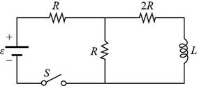
Figure (1)
The net resistance for parallel combination is,
Here,
The net resistance is connected in series with
Here,
Substitute
Substitute
Formula to calculate the current of battery is,
Here,
Substitute
The voltage across the parallel combination of resistors is,
Substitute
Formula to calculate the current though the inductor is,
Substitute
Conclusion:
Therefore, the current carried by the inductor for
(c)
The energy stored in the inductor.
(c)
Answer to Problem 32.64AP
Explanation of Solution
Given info: The induced voltage is
Formula to calculate the energy stored in the inductor is,
Substitute
Thus, the energy stored in the inductor for
Conclusion:
Therefore, the energy stored in the inductor for
(d)
The energy previously stored in the inductor after the switch is opened.
(d)
Answer to Problem 32.64AP
Explanation of Solution
Given info: The induced voltage is
When switch is opened, the energy stored in the inductor will dissipate through resistor
Conclusion:
Therefore, the energy becomes
(e)
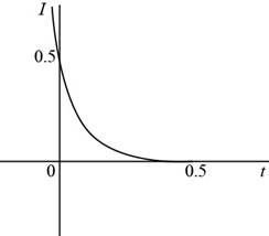
To draw: The graph of the current in the inductor for
(e)
Answer to Problem 32.64AP
Answer The graph of the current in the inductor for
Explanation of Solution
Introduction:
The graph of the current verses time shows the variation of the current in the circuit with time and tells the nature of the current.
Explanation:
Given info: The induced voltage is
After time
Formula to calculate the time constant is,
Substitute
Substitute
The current flowing through the inductor at time
Substitute
Thus, the graph of the current (the initial and final values) in the inductor for
Figure (2)
The graph shows that current decays with exponentially with time constant. The current decreases from
Want to see more full solutions like this?
Chapter 32 Solutions
Physics for Scientists and Engineers, Technology Update (No access codes included)


- Can someone help me with this question. Thanks.arrow_forwardIdentical rays of light enter three transparent blocks composed of different materials. Light slows down upon entering the blocks.arrow_forwardFor single-slit diffraction, calculate the first three values of (the total phase difference between rays from each edge of the slit) that produce subsidiary maxima by a) using the phasor model, b) setting dr = 0, where I is given by, I = Io (sin (10) ². 2arrow_forward
 Physics for Scientists and Engineers, Technology ...PhysicsISBN:9781305116399Author:Raymond A. Serway, John W. JewettPublisher:Cengage Learning
 Principles of Physics: A Calculus-Based TextPhysicsISBN:9781133104261Author:Raymond A. Serway, John W. JewettPublisher:Cengage Learning
 Physics for Scientists and EngineersPhysicsISBN:9781337553278Author:Raymond A. Serway, John W. JewettPublisher:Cengage Learning
 Physics for Scientists and Engineers with Modern ...PhysicsISBN:9781337553292Author:Raymond A. Serway, John W. JewettPublisher:Cengage Learning
 Physics for Scientists and Engineers: Foundations...PhysicsISBN:9781133939146Author:Katz, Debora M.Publisher:Cengage Learning
 College PhysicsPhysicsISBN:9781285737027Author:Raymond A. Serway, Chris VuillePublisher:Cengage Learning