
Videos
A water trough of semicircular cross section of radius 0.6 m consists of two symmetric parts hinged to each other at the bottom, as shown in Fig. P3-72. The two pans are held together by a cable and turnbuckle placed every 3 m along the length of the trough. Calculate the tension in each cable when the trough is filled to the rim.
The tension in the cable.
Answer to Problem 72P
The tension in the cable is
Explanation of Solution
Given information:
A water trough of semicircular cross section of two symmetric parts hinged at each other at the bottom and held together by a cable.
The figure below shows the free body diagram of the right-hand side part of water trough.
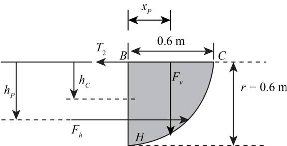
Figure-(1)
Write the Equation for the horizontal hydrostatic force on the part.
Here, density of fluid is
Write the Equation for vertical projected area.
Here, radius of the quarter circle is
Substitute
Write the Equation of the vertical force for curved surface.
Here volume of fluid above curved surface is
Write the Expression for volume of fluid above curved surface.
Substitute
Write the Expression for centre of pressure.
Write the Expression for moment of Inertia.
Substitute
Write the moment Equation about the hinge point.
Here, distance between the line of action of vertical force and hinged point is
Write the Expression for distance between the line of action of vertical force and hinged point.
Substitute
The figure below shows the free body diagram of water trough.
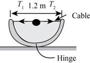
Figure-(2)
Write the expression for horizontal force equilibrium.
Figure-(2)
Calculation:
Substitute
Substitute,
Substitute
Substitute
Substitute
Substitute
Substitute
Here the tension value is same
Conclusion:
The tension in the cable is
Want to see more full solutions like this?
Chapter 3 Solutions
Fluid Mechanics: Fundamentals and Applications


- (Read image)arrow_forward(Read Image)arrow_forwardM16x2 grade 8.8 bolts No. 25 C1- Q.2. The figure is a cross section of a grade 25 cast-iron pressure vessel. A total of N, M16x2.0 grade 8.8 bolts are to be used to resist a separating force of 160 kN. (a) Determine ks, km, and C. (b) Find the number of bolts required for a load factor of 2 where the bolts may be reused when the joint 19 mm is taken apart. (c) with the number of bolts obtained in (b), determine the realized load factor for overload, the yielding factor of safety, and the separation factor of safety. 19 mmarrow_forward
- Problem4. The thin uniform disk of mass m = 1-kg and radius R = 0.1m spins about the bent shaft OG with the angular speed w2 = 20 rad/s. At the same time, the shaft rotates about the z-axis with the angular speed 001 = 10 rad/s. The angle between the bent portion of the shaft and the z-axis is ẞ = 35°. The mass of the shaft is negligible compared to the mass of the disk. a. Find the angular momentum of the disk with respect to point G, based on the axis orientation as shown. Include an MVD in your solution. b. Find the angular momentum of the disk with respect to point O, based on the axis orientation as shown. (Note: O is NOT the center of fixed-point rotation.) c. Find the kinetic energy of the assembly. z R R 002 2R x Answer: H = -0.046ĵ-0.040 kg-m²/sec Ho=-0.146-0.015 kg-m²/sec T 0.518 N-m =arrow_forwardProblem 3. The assembly shown consists of a solid sphere of mass m and the uniform slender rod of the same mass, both of which are welded to the shaft. The assembly is rotating with angular velocity w at a particular moment. Find the angular momentum with respect to point O, in terms of the axes shown. Answer: Ñ。 = ½mc²wcosßsinßĵ + (}{mr²w + 2mb²w + ½ mc²wcos²ß) k 3 m r b 2 C لا marrow_forwardOnly question 2arrow_forward
- Only question 1arrow_forwardOnly question 3arrow_forwardI have Euler parameters that describe the orientation of N relative to Q, e = -0.7071*n3, e4 = 0.7071. I have Euler parameters that describe the orientation of U relative to N, e = -1/sqrt(3)*n1, e4 = sqrt(2/3). After using euler parameter rule of successive rotations, I get euler parameters that describe the orientation of U relative to Q, e = -0.4082*n1 - 0.4082*n2 - 0.5774*n3. I need euler parameters that describe the orientation of U relative to Q in vector basis of q instead of n. How do I get that?arrow_forward
- Describe at least 4 processes in engineering where control charts are (or should be) appliedarrow_forwardDescribe at least two (2) processes where control charts are (or should be) applied.arrow_forwardProblem 3: A cube-shaped spacecraft is in a circular Earth orbit. Let N (n,) be inertial and the spacecraft is denoted S (ŝ₁). The spacecraft is described such that ¯½º = J ŝ₁ŝ₁ + J ŝ₂§₂ + J §¸Ŝ3 Location of the spacecraft in the orbit is determined by the orbit-fixed unit vectors ê, that are oriented by the angle (Qt), where is a constant angular rate. 52 €3 3> 2t 55 Λ Из At the instant when Qt = 90°, the spacecraft S is oriented relative to the orbit such that 8₁ = 0° Space-three 1-2-3 angles 0₂ = 60° and ES = $₂ rad/s 0₁ = 135° (a) At this instant, determine the direction cosine matrix that describes the orientation of the spacecraft with respect to the inertial frame N.arrow_forward
 International Edition---engineering Mechanics: St...Mechanical EngineeringISBN:9781305501607Author:Andrew Pytel And Jaan KiusalaasPublisher:CENGAGE L