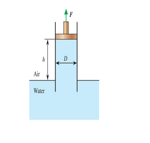
Water from a reservoir is raised in a vertical tube of internal diameter D =30 cm under the influence of the pulling force F of a piston. Determine the force needed to raise the water to a height of h = 1.5 m above the free surface. What would your response be for h = 3 m? Also, taking the atmospheric pressure to be 96 kPa, plot the absolute water pressure at the piston face as h varies from 0 to 3 m.

FIGURE P3-26
The force needed to raise the water to a height of
The force needed to raise the water to a height of
The force needed to raise the water to a height of
Answer to Problem 26P
The force needed to raise the water to a height of
The force needed to raise the water to a height of
The force needed to raise the water to a height of
Explanation of Solution
Given information:
The internal diameter of the piston is
Write the expression for the pressure exerted by a fluid
Here, the pressure exerted by a fluid is
Write the expression for area.
Here, cross-section area of the piston is
Here, weight exerted by the fluid column is
Substitute the
Write the expression for net vertical force.
Here, force required to raise the water is
Write the expression for absolute pressure acting on the piston face.
Here, absolute pressure is
Calculation:
Substitute
Substitute
Substitute
Here, the force required to raise the water is at height of
Substitute
Substitute
Substitute
Here, the force required to raise the water is at height of
Substitute
Substitute
Substitute
Here, the force required to raise the water is at height of
Substitute
Here, absolute pressure at height
Substitute
Here, absolute pressure at height
Substitute
Here, absolute pressure at height
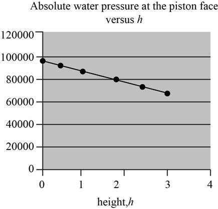
The following Table-(1) shows the water pressure at different height of water level in the tube.
| Water level | Absolute Pressure |
The following figure variation of absolute water verse height of water in the tube.

Figure-(1)
Conclusion:
The force needed to raise the water to a height of
The force needed to raise the water to a height of
The force needed to raise the water to a height of
Want to see more full solutions like this?
Chapter 3 Solutions
Fluid Mechanics: Fundamentals and Applications
- auto controlsarrow_forward1 Pleasearrow_forwardA spring cylinder system measures the pressure. Determine which spring can measure pressure between 0-1 MPa with a large excursion. The plate has a diameter of 20 mm. Also determine the displacement of each 0.1 MPa step.Spring power F=c x fF=Springpower(N)c=Spring constant (N/mm)f=Suspension (mm) How do I come up with right answer?arrow_forward
- A lift with a counterweight is attached to the ceiling. The attachment is with 6 stainless and oiled screws. What screw size is required? What tightening torque? - The lift weighs 500 kg and can carry 800 kg. - Counterweight weight 600 kg - Durability class 12.8 = 960 MPa- Safety factor ns=5+-Sr/Fm= 0.29Gr =0.55arrow_forwardKnowing that a force P of magnitude 750 N is applied to the pedal shown, determine (a) the diameter of the pin at C for which the average shearing stress in the pin is 40 MPa, (b) the corresponding bearing stress in the pedal at C, (c) the corresponding bearing stress in each support bracket at C. 75 mm 300 mm- mm A B P 125 mm 5 mm C Darrow_forwardAssume the B frame differs from the N frame through a 90 degree rotation about the second N base vector. The corresponding DCM description is: 1 2 3 4 5 6 9 # adjust the return matrix values as needed def result(): dcm = [0, 0, 0, 0, 0, 0, 0, 0, 0] return dcmarrow_forward
- Find the reaction at A and B The other response I got was not too accurate,I need expert solved answer, don't use Artificial intelligence or screen shot it solvingarrow_forwardNo chatgpt plsarrow_forwardSolve for the reaction of all the forces Don't use artificial intelligence or screen shot it, only expert should solvearrow_forward
- No chatgpt plsarrow_forwardA six cylinder petrol engine has a compression ratio of 5:1. The clearance volume of each cylinder is 110CC. It operates on the four-stroke constant volume cycle and the indicated efficiency ratio referred to air standard efficiency is 0.56. At the speed of 2400 rpm. 44000KJ/kg. Determine the consumes 10kg of fuel per hour. The calorific value of fuel average indicated mean effective pressure.arrow_forwardThe members of a truss are connected to the gusset plate as shown in (Figure 1). The forces are concurrent at point O. Take = 90° and T₁ = 7.5 kN. Part A Determine the magnitude of F for equilibrium. Express your answer to three significant figures and include the appropriate units. F= 7.03 Submit ? kN Previous Answers Request Answer × Incorrect; Try Again; 21 attempts remaining ▾ Part B Determine the magnitude of T2 for equilibrium. Express your answer to three significant figures and include the appropriate units. Figure T₂ = 7.03 C T2 |? KN Submit Previous Answers Request Answer × Incorrect; Try Again; 23 attempts remaining Provide Feedbackarrow_forward
 Elements Of ElectromagneticsMechanical EngineeringISBN:9780190698614Author:Sadiku, Matthew N. O.Publisher:Oxford University Press
 Mechanics of Materials (10th Edition)Mechanical EngineeringISBN:9780134319650Author:Russell C. HibbelerPublisher:PEARSON
 Thermodynamics: An Engineering ApproachMechanical EngineeringISBN:9781259822674Author:Yunus A. Cengel Dr., Michael A. BolesPublisher:McGraw-Hill Education
 Control Systems EngineeringMechanical EngineeringISBN:9781118170519Author:Norman S. NisePublisher:WILEY
 Mechanics of Materials (MindTap Course List)Mechanical EngineeringISBN:9781337093347Author:Barry J. Goodno, James M. GerePublisher:Cengage Learning
 Engineering Mechanics: StaticsMechanical EngineeringISBN:9781118807330Author:James L. Meriam, L. G. Kraige, J. N. BoltonPublisher:WILEY


