Figure 3.32 shows the oneline diagram of a three-phase power system. By selecting a common base of 100 MVA and 22 kV on the generator side, draw an impedance diagram showing all impedances including the load impedance in per-unit. The data are given a follows: G : 90MVA 22kV x = 0 .18 per unit T 1 : 50MVA 22/220kV x = 0 .10 per unit T 2 : 40MVA 220/11kV x = 0 .06 per unit T 3 : 40MVA 22/110kV x = 0 .064 per unit T 4 : 40MVA 110/11kV x = 0 .08 per unit M : 66 .5MVA 10 .45kV x = 0 .185 per unit Lines I and 2 have series reactance’s of 48.4 and 65.43 Ω , respectively. At bus 4, the three-phase load absorbs 57 MVA at 10.45 kV and 0.6 power factor lagging.
Figure 3.32 shows the oneline diagram of a three-phase power system. By selecting a common base of 100 MVA and 22 kV on the generator side, draw an impedance diagram showing all impedances including the load impedance in per-unit. The data are given a follows: G : 90MVA 22kV x = 0 .18 per unit T 1 : 50MVA 22/220kV x = 0 .10 per unit T 2 : 40MVA 220/11kV x = 0 .06 per unit T 3 : 40MVA 22/110kV x = 0 .064 per unit T 4 : 40MVA 110/11kV x = 0 .08 per unit M : 66 .5MVA 10 .45kV x = 0 .185 per unit Lines I and 2 have series reactance’s of 48.4 and 65.43 Ω , respectively. At bus 4, the three-phase load absorbs 57 MVA at 10.45 kV and 0.6 power factor lagging.
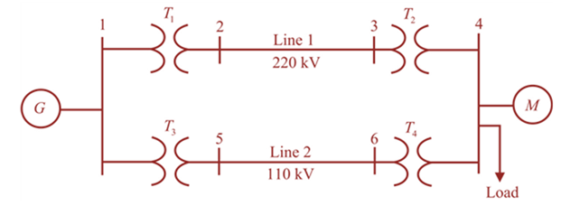
Figure 3.32 shows the oneline diagram of a three-phase power system. By selecting a common base of 100 MVA and 22 kV on the generator side, draw an impedance diagram showing all impedances including the load impedance in per-unit. The data are given a follows:
G
:
90MVA
22kV
x
=
0
.18
per
unit
T
1
:
50MVA
22/220kV
x
=
0
.10
per
unit
T
2
:
40MVA
220/11kV
x
=
0
.06
per
unit
T
3
:
40MVA
22/110kV
x
=
0
.064
per
unit
T
4
:
40MVA
110/11kV
x
=
0
.08
per
unit
M
:
66
.5MVA
10
.45kV
x
=
0
.185
per
unit
Lines I and 2 have series reactance’s of 48.4 and
65.43
Ω
, respectively. At bus 4, the three-phase load absorbs 57 MVA at 10.45 kV and 0.6 power factor lagging.
f. The figure below shows two stage RC coupled amplifier. If the input resistance Rin
of each stage is 1kN. (B = 100). Determine its overall voltage gain. (5 marks)
+15V
ΣΚΩ
kn
10kΩ
10ΚΩ
output
35 ΚΩ
2ΚΩ
5kЛ
2ΚΩ
NO AI PLEASE
Chapter 3 Solutions
MindTap Engineering for Glover/Overbye/Sarma's Power System Analysis and Design, 6th Edition, [Instant Access], 1 term (6 months)
Need a deep-dive on the concept behind this application? Look no further. Learn more about this topic, computer-science and related others by exploring similar questions and additional content below.
![MindTap Engineering for Glover/Overbye/Sarma's Power System Analysis and Design, 6th Edition, [Instant Access], 1 term (6 months)](https://s3.amazonaws.com/compass-isbn-assets/textbook_empty_images/large_textbook_empty.svg)


 Power System Analysis and Design (MindTap Course ...Electrical EngineeringISBN:9781305632134Author:J. Duncan Glover, Thomas Overbye, Mulukutla S. SarmaPublisher:Cengage Learning