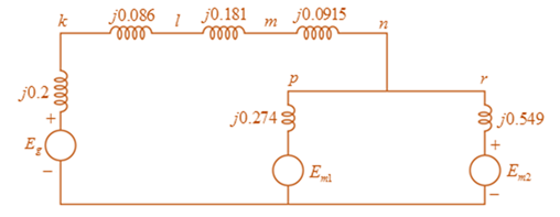
Figure 3.39 shows a oneline diagram of a system in which the three-phase generator is rated 300 MVA, 20 kV with a subtransient reactance of 0.2 per unit and with its neutral grounded through a 0.4 -Ω reactor. The transmission line is 64km long with a cries reactance of 0.5 -Ω/km . The three-phase transformer T 1 is rated 35 0 MVA . 230/ 2 0 kV with a leakage reactance of 0.1 per unit. Transformer T 2 is composed of three single-phase transformers, each rated 100 MVA, 127 / 13 . 2 kV with a leakage reactance of 0.1 per unit. Two 13 . 2 − kV motors M 1 and M 2 with a subtransient reactance of 0.2 per unit for each motor represent the load. M 1 has a rated input of 200 MVA with its neutral grounded through a 0.4 -Ω current-limiting reactor, M 2 has a rated input of 100 MVA with its neutral not connected to ground. Neglect phase shifts associated with the transformers. Choose the generator rating as base in the generator circuit and draw the positive-sequence reactance diagram showing all reactances in per unit.
Figure 3.39 shows a oneline diagram of a system in which the three-phase generator is rated 300 MVA, 20 kV with a subtransient reactance of 0.2 per unit and with its neutral grounded through a 0.4 -Ω reactor. The transmission line is 64km long with a cries reactance of 0.5 -Ω/km . The three-phase transformer T 1 is rated 35 0 MVA . 230/ 2 0 kV with a leakage reactance of 0.1 per unit. Transformer T 2 is composed of three single-phase transformers, each rated 100 MVA, 127 / 13 . 2 kV with a leakage reactance of 0.1 per unit. Two 13 . 2 − kV motors M 1 and M 2 with a subtransient reactance of 0.2 per unit for each motor represent the load. M 1 has a rated input of 200 MVA with its neutral grounded through a 0.4 -Ω current-limiting reactor, M 2 has a rated input of 100 MVA with its neutral not connected to ground. Neglect phase shifts associated with the transformers. Choose the generator rating as base in the generator circuit and draw the positive-sequence reactance diagram showing all reactances in per unit.
Figure 3.39 shows a oneline diagram of a system in which the three-phase generator is rated 300 MVA, 20 kV with a subtransient reactance of 0.2 per unit and with its neutral grounded through a
0.4
-Ω
reactor. The transmission line is 64km long with a cries reactance of
0.5
-Ω/km
. The three-phase transformer
T
1
is rated
35
0
MVA
.
230/
2
0
kV
with a leakage reactance of 0.1 per unit. Transformer
T
2
is composed of three single-phase transformers, each rated 100 MVA,
127
/
13
.
2
kV
with a leakage reactance of 0.1 per unit. Two
13
.
2
−
kV
motors
M
1
and
M
2
with a subtransient reactance of 0.2 per unit for each motor represent the load.
M
1
has a rated input of 200 MVA with its neutral grounded through a
0.4
-Ω
current-limiting reactor,
M
2
has a rated input of 100 MVA with its neutral not connected to ground. Neglect phase shifts associated with the transformers. Choose the generator rating as base in the generator circuit and draw the positive-sequence reactance diagram showing all reactances in per unit.
Matched filter in the frequency domain
(1.5) (a) Consider the signal s(t) in 3(c). Assuming that the unit of time is a millisecond
and the desired frequency resolution is 1 Hz, use the function contFT to compute
and plot |S(f).
(b) Use the function contFT to compute and plot the magnitude of the Fourier trans-
form of the convolution s * SMF numerically computed in 3(d). Also plot for
comparison |S(f)12, using the output of 5(a). The two plots should match.
(c) Plot the phase of the Fourier transform of s✶ SMF obtained in 5(b). Comment on
whether the plot matches your expectations.
Find Eigenvalues and Eigenvectors for the following matrices:
[10
4
A=0
2
0
3
1
1 -3
1. (20 pts) Plot the pulse and the FFT for a pulse with the following properties at x=0 and x=10
cm.
f=2 MHz
m=3
Ncyc=2, 6, 20
po 1 MPa (source pressure)
x=10 cm (propagates in a Newtonian fluid for 10 cm as a plane wave-not a sound beam)
a=0.5 dB/(MHz cm)
Consider 3 types of waves: sine, square, and sawtooth. (square and sawtooth only for grad
students)
Observe your plots and draw some conclusions. Discuss any possible issues you encounter.
2. (20 pts) We have the following 3 ultrasonic transducers:
a. Focused 1 MHz, 2.54 cm diameter, 5.08 cm focus
b. Focused 3 MHz, 2.54 cm diameter, 5.08 cm focus
c. Unfocused 0.1 MHz, 2.54 cm diameter
The transducers are operating in water (c=1486 m/s).
I. Plot the axial field for all transducers
II. Plot the focal transverse field for the focused transducers and the transverse field at the
Rayleigh distance (R_0) and at 2R_0 for the unfocused.
III. Assume source pressure of 0.1 MPa, and find the acoustic pressure in MPa at the location
(r=0, z=4.5…
Chapter 3 Solutions
MindTap Engineering for Glover/Overbye/Sarma's Power System Analysis and Design, 6th Edition, [Instant Access], 1 term (6 months)
Need a deep-dive on the concept behind this application? Look no further. Learn more about this topic, computer-science and related others by exploring similar questions and additional content below.
![MindTap Engineering for Glover/Overbye/Sarma's Power System Analysis and Design, 6th Edition, [Instant Access], 1 term (6 months)](https://s3.amazonaws.com/compass-isbn-assets/textbook_empty_images/large_textbook_empty.svg)


 Power System Analysis and Design (MindTap Course ...Electrical EngineeringISBN:9781305632134Author:J. Duncan Glover, Thomas Overbye, Mulukutla S. SarmaPublisher:Cengage Learning