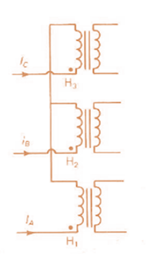
Consider the three single-phase two-winding transformers shown in Figure 3.37. The high-voltage windings are connected in Y. (a) For the low-voltage side, connect the windings in Δ , place the polarity marks, and label the terminals a , b , and c in accordance with the American standard. (b) Relabel the terminals a’ , b’ , and c’ such that V A N is 90 ° out of phase with V a ' η for positive sequence.
Consider the three single-phase two-winding transformers shown in Figure 3.37. The high-voltage windings are connected in Y. (a) For the low-voltage side, connect the windings in Δ , place the polarity marks, and label the terminals a , b , and c in accordance with the American standard. (b) Relabel the terminals a’ , b’ , and c’ such that V A N is 90 ° out of phase with V a ' η for positive sequence.
Solution Summary: The author explains how to label the terminals a, b and c according to the American standards.
Consider the three single-phase two-winding transformers shown in Figure 3.37. The high-voltage windings are connected in Y. (a) For the low-voltage side, connect the windings in
Δ
, place the polarity marks, and label the terminals a, b, and c in accordance with the American standard. (b) Relabel the terminals a’, b’, and c’ such that
V
A
N
is
90
°
out of phase with
V
a
'
η
for positive sequence.
Example2:-
8. = e.A nia +2.1 =
Find the maximum steady-state power capability of a system consisting of a
generator equivalent reactance of 0.4pu connected to an infinite bus through a
series reactance of 1.0 p.u. The terminal voltage of the generator is held at1.10 p.u.
and the voltage of the infinite bus is 1.0 p.u.
B) A 60-Hz generator is supplying 60% of P max to an infinite bus through a reactive network.
A fault occurs which increases the reactance of the network between the generator internal
voltage and the infinite bus by 400%. When the fault is cleared, the maximum power that can
be delivered is 80% of the original maximum value. Determine the critical clearing angle for
the condition described.
In the circuit shown, let Vs-9, R₁-8, R2-2, and R3-4. Use Nodal analysis to determine the current lo. In
particular find:
V2=
10=
A
The relative tolerance for this problem is 5 %.
R₁
V₁
+
ww
R₂
Vs
V₂
21
x
R3
Chapter 3 Solutions
MindTap Engineering for Glover/Overbye/Sarma's Power System Analysis and Design, 6th Edition, [Instant Access], 1 term (6 months)
Need a deep-dive on the concept behind this application? Look no further. Learn more about this topic, computer-science and related others by exploring similar questions and additional content below.
![MindTap Engineering for Glover/Overbye/Sarma's Power System Analysis and Design, 6th Edition, [Instant Access], 1 term (6 months)](https://s3.amazonaws.com/compass-isbn-assets/textbook_empty_images/large_textbook_empty.svg)


 Power System Analysis and Design (MindTap Course ...Electrical EngineeringISBN:9781305632134Author:J. Duncan Glover, Thomas Overbye, Mulukutla S. SarmaPublisher:Cengage Learning