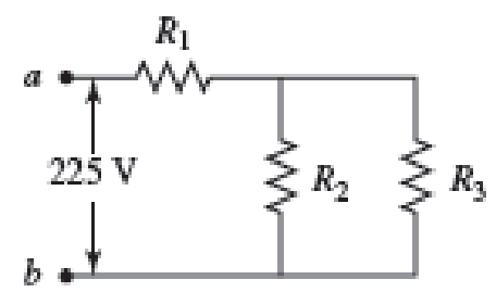
Three resistors with resistances R1 = R/2 and R2 = R3 = R are connected as shown, and a potential difference of 225 V is applied across terminals a and b (Fig. P29.49).
a. If the resistor R1 dissipates 75.0 W of power, what is the value of R?
b. What is the total power supplied to the circuit by the emf?
c. What is the potential difference across each of the three resistors?

(a)
Find the value of resistance from the given circuit.
Answer to Problem 49PQ
The value of
Explanation of Solution
Refer the figure
Write the equivalent resistance of the parallel circuit as.
Here
Since
Write the equivalent resistance of circuit as.
Here,
Write the expression for the current drawn by the circuit from the voltage applied as.
Here
Write the expression for power dissipated across
Here,
Conclusion:
Substitute
Rearrange the terms in above equation
Substitute
Substitute
Substitute
Rearrange the terms in above equation
Thus, the value of
(b)
Find the total power supplied to the circuit.
Answer to Problem 49PQ
The total power supplied to the circuit is
Explanation of Solution
The total power supplied to the circuit is given as
Here
Conclusion:
Substitute
Substitute
Thus, the total power supplied to the circuit is
(c)
Find the potential difference across the three resistors.
Answer to Problem 49PQ
The potential difference across the resistance
Explanation of Solution
Write the expression for the potential difference across the resistance
Here
Write the expression for the remaining potential drop is across the parallel combination of
Here
Conclusion:
Substitute
Substitute
Thus, the potential difference across the resistance
Want to see more full solutions like this?
Chapter 29 Solutions
Physics for Scientists and Engineers: Foundations and Connections
- look at answer show all work step by steparrow_forwardLook at the answer and please show all work step by steparrow_forward3. As a woman, who's eyes are h = 1.5 m above the ground, looks down the road sees a tree with height H = 9.0 m. Below the tree is what appears to be a reflection of the tree. The observation of this apparent reflection gives the illusion of water on the roadway. This effect is commonly called a mirage. Use the results of questions 1 and 2 and the principle of ray reversibility to analyze the diagram below. Assume that light leaving the top of the tree bends toward the horizontal until it just grazes ground level. After that, the ray bends upward eventually reaching the woman's eyes. The woman interprets this incoming light as if it came from an image of the tree. Determine the size, H', of the image. (Answer 8.8 m) please show all work step by steparrow_forward
 Physics for Scientists and Engineers: Foundations...PhysicsISBN:9781133939146Author:Katz, Debora M.Publisher:Cengage Learning
 Physics for Scientists and EngineersPhysicsISBN:9781337553278Author:Raymond A. Serway, John W. JewettPublisher:Cengage Learning
 Physics for Scientists and Engineers with Modern ...PhysicsISBN:9781337553292Author:Raymond A. Serway, John W. JewettPublisher:Cengage Learning
 Physics for Scientists and Engineers, Technology ...PhysicsISBN:9781305116399Author:Raymond A. Serway, John W. JewettPublisher:Cengage Learning


