Physics for Scientists and Engineers: Foundations and Connections
1st Edition
ISBN: 9781133939146
Author: Katz, Debora M.
Publisher: Cengage Learning
expand_more
expand_more
format_list_bulleted
Textbook Question
Chapter 29, Problem 27PQ
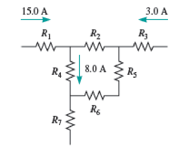
Determine the currents through the resistors R2, R5, R6, and R7 in the set of junctions and branches shown in Figure P29.27. Hint: Use Kirchhoff’s junction rule, be sure to consider the branches where a current is shown, and assume the branches that appear disconnected are connected to other parts of the circuit.

FIGURE P29.27
Expert Solution & Answer
Want to see the full answer?
Check out a sample textbook solution
Students have asked these similar questions
Can someone help me
Need help on the following questions on biomechanics. (Please refer to images below)A gymnast weighing 68 kg attempts a handstand using only one arm. He plants his handat an angle resulting in the reaction force shown.A) Find the resultant force (acting on the Center of Mass)B) Find the resultant moment (acting on the Center of Mass)C) Draw the resultant force and moment about the center of mass on the figure below. Will the gymnast rotate, translate, or both? And in which direction?
Please help me on the following question (Please refer to image below)An Olympic lifter (m = 103kg) is holding a lift with a mass of 350 kg. The barexerts a purely vertical force that is equally distributed between both hands. Each arm has amass of 9 kg, are 0.8m long and form a 40° angle with the horizontal. The CoM for each armis 0.5 m from hand. Assuming the lifter is facing us in the diagram below, his right deltoidinserts 14cm from the shoulder at an angle of 13° counter-clockwise from the humerus.A) You are interested in calculating the force in the right deltoid. Draw a free body diagramof the right arm including the external forces, joint reaction forces, a coordinate system andstate your assumptions.B) Find the force exerted by the right deltoidC) Find the shoulder joint contact force. Report your answer using the magnitude and directionof the shoulder force vector.
Chapter 29 Solutions
Physics for Scientists and Engineers: Foundations and Connections
Ch. 29.1 - What are the SI units of ?Ch. 29.1 - Prob. 29.2CECh. 29.2 - Prob. 29.3CECh. 29.4 - Prob. 29.5CECh. 29.4 - Prob. 29.6CECh. 29.5 - Prob. 29.7CECh. 29 - Study the symbols in Table 29.2. Then, without...Ch. 29 - Prob. 2PQCh. 29 - Prob. 3PQCh. 29 - Suppose you need to measure the potential...
Ch. 29 - Prob. 5PQCh. 29 - Prob. 6PQCh. 29 - A real battery (modeled as an ideal emf device in...Ch. 29 - Prob. 8PQCh. 29 - Two circuits made up of identical ideal emf...Ch. 29 - Prob. 10PQCh. 29 - Prob. 11PQCh. 29 - Prob. 12PQCh. 29 - Eight real batteries, each with an emf of 5.00 V...Ch. 29 - Prob. 14PQCh. 29 - Prob. 15PQCh. 29 - Prob. 16PQCh. 29 - Prob. 17PQCh. 29 - Prob. 18PQCh. 29 - Prob. 19PQCh. 29 - An ideal emf device with emf is connected to two...Ch. 29 - Prob. 21PQCh. 29 - Prob. 22PQCh. 29 - Prob. 23PQCh. 29 - Prob. 24PQCh. 29 - Prob. 25PQCh. 29 - Prob. 26PQCh. 29 - Determine the currents through the resistors R2,...Ch. 29 - The emf devices in the circuits shown in Figure...Ch. 29 - Prob. 29PQCh. 29 - Prob. 30PQCh. 29 - Prob. 31PQCh. 29 - Prob. 32PQCh. 29 - Prob. 33PQCh. 29 - Prob. 34PQCh. 29 - A Figure P29.35 shows a combination of six...Ch. 29 - A Each resistor shown in Figure P29.36 has...Ch. 29 - Each resistor shown in Figure P29.36 has a...Ch. 29 - Prob. 38PQCh. 29 - Prob. 39PQCh. 29 - The emf in Figure P29.40 is 4.54 V. The...Ch. 29 - Figure P29.41 shows three resistors (R1 = 14.0 ,...Ch. 29 - Figure P29.42 shows five resistors and two...Ch. 29 - The emfs in Figure P29.43 are 1 = 6.00 V and 2 =...Ch. 29 - Prob. 44PQCh. 29 - Figure P29.45 shows five resistors connected...Ch. 29 - Figure P29.46 shows a circuit with a 12.0-V...Ch. 29 - Two ideal emf devices are connected to a set of...Ch. 29 - Two ideal emf devices are connected to a set of...Ch. 29 - Three resistors with resistances R1 = R/2 and R2 =...Ch. 29 - Prob. 51PQCh. 29 - Prob. 52PQCh. 29 - Prob. 53PQCh. 29 - Prob. 55PQCh. 29 - At time t = 0, an RC circuit consists of a 12.0-V...Ch. 29 - A 210.0- resistor and an initially uncharged...Ch. 29 - Prob. 58PQCh. 29 - A real battery with internal resistance 0.500 and...Ch. 29 - Figure P29.60 shows a simple RC circuit with a...Ch. 29 - Prob. 61PQCh. 29 - Prob. 62PQCh. 29 - Prob. 63PQCh. 29 - Ralph has three resistors, R1, R2, and R3,...Ch. 29 - Prob. 65PQCh. 29 - An ideal emf device is connected to a set of...Ch. 29 - Prob. 67PQCh. 29 - An ideal emf device (24.0 V) is connected to a set...Ch. 29 - Prob. 69PQCh. 29 - What is the equivalent resistance between points a...Ch. 29 - A capacitor with initial charge Q0 is connected...Ch. 29 - Prob. 73PQCh. 29 - Prob. 74PQCh. 29 - Prob. 75PQCh. 29 - Prob. 76PQCh. 29 - Figure P29.77 shows a circuit with two batteries...Ch. 29 - In the RC circuit shown in Figure P29.78, an ideal...Ch. 29 - Prob. 79PQCh. 29 - Calculate the equivalent resistance between points...Ch. 29 - In Figure P29.81, N real batteries, each with an...Ch. 29 - Prob. 82PQCh. 29 - Prob. 83PQCh. 29 - Prob. 84PQCh. 29 - Figure P29.84 shows a circuit that consists of two...Ch. 29 - Prob. 86PQCh. 29 - Prob. 87PQCh. 29 - Prob. 88PQCh. 29 - Prob. 89PQCh. 29 - Prob. 90PQCh. 29 - Prob. 91PQCh. 29 - Prob. 92PQCh. 29 - Prob. 93PQCh. 29 - Prob. 94PQCh. 29 - Prob. 95PQ
Knowledge Booster
Learn more about
Need a deep-dive on the concept behind this application? Look no further. Learn more about this topic, physics and related others by exploring similar questions and additional content below.Similar questions
- I need help with part B. I cant seem to get the correct answer. Please walk me through what youre doing to get to the answer and what that could bearrow_forwardQuestion 6: Chlorine is widely used to purify municipal water supplies and to treat swimming pool waters. Suppose that the volume of a particular sample of Cl₂ gas is 8.70 L at 895 torr and 24°C. (a) How many grams of Cl₂ are in the sample? ⚫ Atomic mass of CI = 35.453 g/mol • Molar mass of Cl₂ = 2 x 35.453 = 70.906 g/mol Solution: Use the Ideal Gas Law: Step 1: Convert Given Values • Pressure: P = 895 torr → atm PV= = nRT 1 P = 895 × = 1.1789 atm 760 • Temperature: Convert to Kelvin: T24273.15 = 297.15 K • Gas constant: R = 0.0821 L atm/mol. K Volume: V = 8.70 L Step 2: Solve for n . PV n = RT n = (1.1789)(8.70) (0.0821)(297.15) 10.25 n = = 0.420 mol 24.405 Step 3: Calculate Mass of Cl₂ Final Answer: 29.78 g of Cl₂. mass nx M mass= (0.420)(70.906) mass= 29.78 garrow_forwardE1 R₁ w 0.50 20 Ω 12 R₁₂ ww ΒΩ R₂ 60 E3 C RA w 15 Ω E2 0.25 E4 0.75 Ω 0.5 Ωarrow_forward
- What is the force (in N) on the 2.0 μC charge placed at the center of the square shown below? (Express your answer in vector form.) 5.0 με 4.0 με 2.0 με + 1.0 m 1.0 m -40 με 2.0 μCarrow_forwardWhat is the force (in N) on the 5.4 µC charge shown below? (Express your answer in vector form.) −3.1 µC5.4 µC9.2 µC6.4 µCarrow_forwardAn ideal gas in a sealed container starts out at a pressure of 8900 N/m2 and a volume of 5.7 m3. If the gas expands to a volume of 6.3 m3 while the pressure is held constant (still at 8900 N/m2), how much work is done by the gas? Give your answer as the number of Joules.arrow_forward
arrow_back_ios
SEE MORE QUESTIONS
arrow_forward_ios
Recommended textbooks for you
 Physics for Scientists and Engineers: Foundations...PhysicsISBN:9781133939146Author:Katz, Debora M.Publisher:Cengage Learning
 Physics for Scientists and Engineers, Technology ...PhysicsISBN:9781305116399Author:Raymond A. Serway, John W. JewettPublisher:Cengage Learning
 Principles of Physics: A Calculus-Based TextPhysicsISBN:9781133104261Author:Raymond A. Serway, John W. JewettPublisher:Cengage Learning
 Physics for Scientists and Engineers with Modern ...PhysicsISBN:9781337553292Author:Raymond A. Serway, John W. JewettPublisher:Cengage Learning
 Physics for Scientists and EngineersPhysicsISBN:9781337553278Author:Raymond A. Serway, John W. JewettPublisher:Cengage Learning

Physics for Scientists and Engineers: Foundations...
Physics
ISBN:9781133939146
Author:Katz, Debora M.
Publisher:Cengage Learning

Physics for Scientists and Engineers, Technology ...
Physics
ISBN:9781305116399
Author:Raymond A. Serway, John W. Jewett
Publisher:Cengage Learning


Principles of Physics: A Calculus-Based Text
Physics
ISBN:9781133104261
Author:Raymond A. Serway, John W. Jewett
Publisher:Cengage Learning

Physics for Scientists and Engineers with Modern ...
Physics
ISBN:9781337553292
Author:Raymond A. Serway, John W. Jewett
Publisher:Cengage Learning

Physics for Scientists and Engineers
Physics
ISBN:9781337553278
Author:Raymond A. Serway, John W. Jewett
Publisher:Cengage Learning
DC Series circuits explained - The basics working principle; Author: The Engineering Mindset;https://www.youtube.com/watch?v=VV6tZ3Aqfuc;License: Standard YouTube License, CC-BY