
Physics for Scientists and Engineers: Foundations and Connections
1st Edition
ISBN: 9781133939146
Author: Katz, Debora M.
Publisher: Cengage Learning
expand_more
expand_more
format_list_bulleted
Videos
Textbook Question
Chapter 29, Problem 68PQ
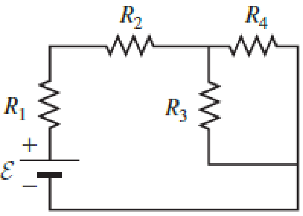
An ideal emf device (24.0 V) is connected to a set of resistors as shown in Figure P29.66. If R1 = 22.5 Ω, R2 = 52.5 Ω, R3 = 125 Ω, and R4 = 75.0 Ω, what is the voltage drop across each resistor?
Expert Solution & Answer

Trending nowThis is a popular solution!

Students have asked these similar questions
No chatgpt pls will upvote Already got wrong chatgpt answer
PART III - RESISTORS IN PARALLEL
Consider (but do not yet build) the circuit shown in the circuit diagram
to the left, which we will call Circuit 3. Make sure you are using Bert
bulbs. You may want to wire two batteries in series rather than use a
single battery.
7. Predict:
a) How will the brightness of bulb B3A compare to the brightness
to bulb B3B?
c)
X
E
B3A
b) How will the brightness of bulb BзA compare to the brightness of bulb B₁ from Circuit 1?
How will the currents at points X, Y, and Z be related?
www
d) How will the current at point X in this circuit compare to the current at point X from Circuit 1?
Y
Z
B3B
www
PART II - RESISTORS IN SERIES
Consider (but do not yet build) the circuit shown in the circuit diagram to the left,
which we will call Circuit 2. Make sure you are using Bert bulbs. You may want
to wire two batteries in series rather than use a single battery.
4. Predict:
a) How will the brightness of bulb B₂ compare to the brighness to bulb
B2B?
X
B2A
E
Y
B2B
Ꮓ
b) How will the brightness of bulb B2A compare to the brightness of bulb B₁ from Circuit 1?
c) How will the currents at points X, Y, and Z be related?
d) How will the current at point X in this circuit compare to the current at point X from Circuit 1?
Chapter 29 Solutions
Physics for Scientists and Engineers: Foundations and Connections
Ch. 29.1 - What are the SI units of ?Ch. 29.1 - Prob. 29.2CECh. 29.2 - Prob. 29.3CECh. 29.4 - Prob. 29.5CECh. 29.4 - Prob. 29.6CECh. 29.5 - Prob. 29.7CECh. 29 - Study the symbols in Table 29.2. Then, without...Ch. 29 - Prob. 2PQCh. 29 - Prob. 3PQCh. 29 - Suppose you need to measure the potential...
Ch. 29 - Prob. 5PQCh. 29 - Prob. 6PQCh. 29 - A real battery (modeled as an ideal emf device in...Ch. 29 - Prob. 8PQCh. 29 - Two circuits made up of identical ideal emf...Ch. 29 - Prob. 10PQCh. 29 - Prob. 11PQCh. 29 - Prob. 12PQCh. 29 - Eight real batteries, each with an emf of 5.00 V...Ch. 29 - Prob. 14PQCh. 29 - Prob. 15PQCh. 29 - Prob. 16PQCh. 29 - Prob. 17PQCh. 29 - Prob. 18PQCh. 29 - Prob. 19PQCh. 29 - An ideal emf device with emf is connected to two...Ch. 29 - Prob. 21PQCh. 29 - Prob. 22PQCh. 29 - Prob. 23PQCh. 29 - Prob. 24PQCh. 29 - Prob. 25PQCh. 29 - Prob. 26PQCh. 29 - Determine the currents through the resistors R2,...Ch. 29 - The emf devices in the circuits shown in Figure...Ch. 29 - Prob. 29PQCh. 29 - Prob. 30PQCh. 29 - Prob. 31PQCh. 29 - Prob. 32PQCh. 29 - Prob. 33PQCh. 29 - Prob. 34PQCh. 29 - A Figure P29.35 shows a combination of six...Ch. 29 - A Each resistor shown in Figure P29.36 has...Ch. 29 - Each resistor shown in Figure P29.36 has a...Ch. 29 - Prob. 38PQCh. 29 - Prob. 39PQCh. 29 - The emf in Figure P29.40 is 4.54 V. The...Ch. 29 - Figure P29.41 shows three resistors (R1 = 14.0 ,...Ch. 29 - Figure P29.42 shows five resistors and two...Ch. 29 - The emfs in Figure P29.43 are 1 = 6.00 V and 2 =...Ch. 29 - Prob. 44PQCh. 29 - Figure P29.45 shows five resistors connected...Ch. 29 - Figure P29.46 shows a circuit with a 12.0-V...Ch. 29 - Two ideal emf devices are connected to a set of...Ch. 29 - Two ideal emf devices are connected to a set of...Ch. 29 - Three resistors with resistances R1 = R/2 and R2 =...Ch. 29 - Prob. 51PQCh. 29 - Prob. 52PQCh. 29 - Prob. 53PQCh. 29 - Prob. 55PQCh. 29 - At time t = 0, an RC circuit consists of a 12.0-V...Ch. 29 - A 210.0- resistor and an initially uncharged...Ch. 29 - Prob. 58PQCh. 29 - A real battery with internal resistance 0.500 and...Ch. 29 - Figure P29.60 shows a simple RC circuit with a...Ch. 29 - Prob. 61PQCh. 29 - Prob. 62PQCh. 29 - Prob. 63PQCh. 29 - Ralph has three resistors, R1, R2, and R3,...Ch. 29 - Prob. 65PQCh. 29 - An ideal emf device is connected to a set of...Ch. 29 - Prob. 67PQCh. 29 - An ideal emf device (24.0 V) is connected to a set...Ch. 29 - Prob. 69PQCh. 29 - What is the equivalent resistance between points a...Ch. 29 - A capacitor with initial charge Q0 is connected...Ch. 29 - Prob. 73PQCh. 29 - Prob. 74PQCh. 29 - Prob. 75PQCh. 29 - Prob. 76PQCh. 29 - Figure P29.77 shows a circuit with two batteries...Ch. 29 - In the RC circuit shown in Figure P29.78, an ideal...Ch. 29 - Prob. 79PQCh. 29 - Calculate the equivalent resistance between points...Ch. 29 - In Figure P29.81, N real batteries, each with an...Ch. 29 - Prob. 82PQCh. 29 - Prob. 83PQCh. 29 - Prob. 84PQCh. 29 - Figure P29.84 shows a circuit that consists of two...Ch. 29 - Prob. 86PQCh. 29 - Prob. 87PQCh. 29 - Prob. 88PQCh. 29 - Prob. 89PQCh. 29 - Prob. 90PQCh. 29 - Prob. 91PQCh. 29 - Prob. 92PQCh. 29 - Prob. 93PQCh. 29 - Prob. 94PQCh. 29 - Prob. 95PQ
Knowledge Booster


Learn more about
Need a deep-dive on the concept behind this application? Look no further. Learn more about this topic, physics and related others by exploring similar questions and additional content below.Similar questions
- No chatgpt pls will upvote Already got wrong chatgpt answerarrow_forwardWhat is the practical benefit (in terms of time savings and efficiency) of defining the potential energy? Be clear about what is required in terms of calculation if we do not use the concept of potential energy.arrow_forwardWhat is the critical angle fir the light travelling from the crown glass(n=1.52) into the air(n=1.00)?arrow_forward
- No chatgpt pls will upvotearrow_forwardYou are working with a team that is designing a new roller coaster-type amusement park ride for a major theme park. You are present for the testing of the ride, in which an empty 150 kg car is sent along the entire ride. Near the end of the ride, the car is at near rest at the top of a 100 m tall track. It then enters a final section, rolling down an undulating hill to ground level. The total length of track for this final section from the top to the ground is 250 m. For the first 230 m, a constant friction force of 370 N acts from computer-controlled brakes. For the last 20 m, which is horizontal at ground level, the computer increases the friction force to a value required for the speed to be reduced to zero just as the car arrives at the point on the track at which the passengers exit. (a) Determine the required constant friction force (in N) for the last 20 m for the empty test car. Write AK + AU + AE int = W+Q + TMW + TMT + TET + TER for the car-track-Earth system and solve for…arrow_forward= 12 kg, and m3 Three objects with masses m₁ = 3.8 kg, m₂ find the speed of m3 after it moves down 4.0 m. m/s 19 kg, respectively, are attached by strings over frictionless pulleys as indicated in the figure below. The horizontal surface exerts a force of friction of 30 N on m2. If the system is released from rest, use energy concepts to m m2 m3 iarrow_forward
- Three objects with masses m₁ = 3.8 kg, m₂ = 12 kg, and m 19 kg, respectively, are attached by strings over frictionless pulleys as indicated in the figure below. The horizontal surface exerts a force of friction of 30 N on m2. If the system is released from rest, use energy concepts to find the speed of m¸ after it moves down 4.0 m. m/s m m2 mgarrow_forwardIn order for Jane to return to base camp, she needs to swing across a river of width D that is filled with alligators. She must swing into a wind exerting constant horizontal force F, F = 110 N, L = 40.0 m, 0 = 50.0°, and her mass to be 50.0 kg. Wind →F Tarzan! Jane (a) with what minimum speed (in m/s) must Jane begin her swing to just make it to the other side? (If Jane can make it across with zero initial velocity, enter 0.) m/s on a vine having length L and initially making an angle with the vertical (see below figure). Take D = 48.0 m, (b) Shortly after Jane's arrival, Tarzan and Jane decide to swing back across the river (simultaneously). With what minimum speed (in m/s) must they begin their swing? Assume that Tarzan has a mass of 80.0 kg. m/sarrow_forwardR=2.00 12V 2.00 4.00 4.002 What is the current in one of the 4.0 Q resistors? An isolated point charge q is located at point X. Two other points Y and Z are such that YZ2 XY. Y X What is (electric field at Y)/(electric field at Z)?arrow_forward
- Two objects (m₁ = 4.75 kg and m₂ 2.80 kg) are connected by a light string passing over a light, frictionless pulley as in the figure below. The 4.75-kg object is released from rest at a point h = 4.00 m above the table mg m (a) Determine the speed of each object when the two pass each other. m/s (b) Determine the speed of each object at the moment the 4.75-kg object hits the table. m/s (c) How much higher does the 2.80-kg object travel after the 4.75-kg object hits the table? marrow_forwardA cell of negligible internal resistance is connected to three identical resistors. The current in the cell is 3.0 A. The resistors are now arranged in series. What is the new current in the cell?arrow_forwardA negatively charged sphere is falling through a magnetic field. north pole of magnet direction of motion south pole of magnet What is the direction of the magnetic force acting on the sphere?arrow_forward
arrow_back_ios
SEE MORE QUESTIONS
arrow_forward_ios
Recommended textbooks for you
 Principles of Physics: A Calculus-Based TextPhysicsISBN:9781133104261Author:Raymond A. Serway, John W. JewettPublisher:Cengage Learning
 Physics for Scientists and Engineers: Foundations...PhysicsISBN:9781133939146Author:Katz, Debora M.Publisher:Cengage Learning
 Physics for Scientists and Engineers, Technology ...PhysicsISBN:9781305116399Author:Raymond A. Serway, John W. JewettPublisher:Cengage Learning
 College PhysicsPhysicsISBN:9781305952300Author:Raymond A. Serway, Chris VuillePublisher:Cengage Learning
 College PhysicsPhysicsISBN:9781285737027Author:Raymond A. Serway, Chris VuillePublisher:Cengage Learning
Principles of Physics: A Calculus-Based Text
Physics
ISBN:9781133104261
Author:Raymond A. Serway, John W. Jewett
Publisher:Cengage Learning
Physics for Scientists and Engineers: Foundations...
Physics
ISBN:9781133939146
Author:Katz, Debora M.
Publisher:Cengage Learning
Physics for Scientists and Engineers, Technology ...
Physics
ISBN:9781305116399
Author:Raymond A. Serway, John W. Jewett
Publisher:Cengage Learning
College Physics
Physics
ISBN:9781305952300
Author:Raymond A. Serway, Chris Vuille
Publisher:Cengage Learning
College Physics
Physics
ISBN:9781285737027
Author:Raymond A. Serway, Chris Vuille
Publisher:Cengage Learning
What is Electromagnetic Induction? | Faraday's Laws and Lenz Law | iKen | iKen Edu | iKen App; Author: Iken Edu;https://www.youtube.com/watch?v=3HyORmBip-w;License: Standard YouTube License, CC-BY