
Physics for Scientists and Engineers: Foundations and Connections
1st Edition
ISBN: 9781133939146
Author: Katz, Debora M.
Publisher: Cengage Learning
expand_more
expand_more
format_list_bulleted
Videos
Textbook Question
Chapter 29, Problem 85PQ
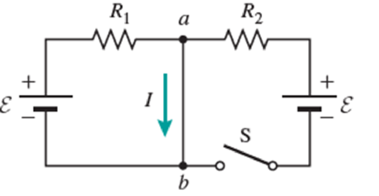
Figure P29.84 shows a circuit that consists of two identical emf devices. If R1 = R2 = R and the switch is closed, find an expression (in terms of R and ε) for the current I that is in the branch from point a to b.
Expert Solution & Answer

Trending nowThis is a popular solution!

Students have asked these similar questions
A ball is shot at an angle of 60° with the ground. What should be the initial velocity of the ball so that it will go inside the ring 8 meters away and 3 meters high. Suppose that you want the ball to be scored exactly at the buzzer, determine the required time to throw and shoot the ball. Full solution and figure if there is.
Correct answer please. I will upvote.
Define operational amplifier
Chapter 29 Solutions
Physics for Scientists and Engineers: Foundations and Connections
Ch. 29.1 - What are the SI units of ?Ch. 29.1 - Prob. 29.2CECh. 29.2 - Prob. 29.3CECh. 29.4 - Prob. 29.5CECh. 29.4 - Prob. 29.6CECh. 29.5 - Prob. 29.7CECh. 29 - Study the symbols in Table 29.2. Then, without...Ch. 29 - Prob. 2PQCh. 29 - Prob. 3PQCh. 29 - Suppose you need to measure the potential...
Ch. 29 - Prob. 5PQCh. 29 - Prob. 6PQCh. 29 - A real battery (modeled as an ideal emf device in...Ch. 29 - Prob. 8PQCh. 29 - Two circuits made up of identical ideal emf...Ch. 29 - Prob. 10PQCh. 29 - Prob. 11PQCh. 29 - Prob. 12PQCh. 29 - Eight real batteries, each with an emf of 5.00 V...Ch. 29 - Prob. 14PQCh. 29 - Prob. 15PQCh. 29 - Prob. 16PQCh. 29 - Prob. 17PQCh. 29 - Prob. 18PQCh. 29 - Prob. 19PQCh. 29 - An ideal emf device with emf is connected to two...Ch. 29 - Prob. 21PQCh. 29 - Prob. 22PQCh. 29 - Prob. 23PQCh. 29 - Prob. 24PQCh. 29 - Prob. 25PQCh. 29 - Prob. 26PQCh. 29 - Determine the currents through the resistors R2,...Ch. 29 - The emf devices in the circuits shown in Figure...Ch. 29 - Prob. 29PQCh. 29 - Prob. 30PQCh. 29 - Prob. 31PQCh. 29 - Prob. 32PQCh. 29 - Prob. 33PQCh. 29 - Prob. 34PQCh. 29 - A Figure P29.35 shows a combination of six...Ch. 29 - A Each resistor shown in Figure P29.36 has...Ch. 29 - Each resistor shown in Figure P29.36 has a...Ch. 29 - Prob. 38PQCh. 29 - Prob. 39PQCh. 29 - The emf in Figure P29.40 is 4.54 V. The...Ch. 29 - Figure P29.41 shows three resistors (R1 = 14.0 ,...Ch. 29 - Figure P29.42 shows five resistors and two...Ch. 29 - The emfs in Figure P29.43 are 1 = 6.00 V and 2 =...Ch. 29 - Prob. 44PQCh. 29 - Figure P29.45 shows five resistors connected...Ch. 29 - Figure P29.46 shows a circuit with a 12.0-V...Ch. 29 - Two ideal emf devices are connected to a set of...Ch. 29 - Two ideal emf devices are connected to a set of...Ch. 29 - Three resistors with resistances R1 = R/2 and R2 =...Ch. 29 - Prob. 51PQCh. 29 - Prob. 52PQCh. 29 - Prob. 53PQCh. 29 - Prob. 55PQCh. 29 - At time t = 0, an RC circuit consists of a 12.0-V...Ch. 29 - A 210.0- resistor and an initially uncharged...Ch. 29 - Prob. 58PQCh. 29 - A real battery with internal resistance 0.500 and...Ch. 29 - Figure P29.60 shows a simple RC circuit with a...Ch. 29 - Prob. 61PQCh. 29 - Prob. 62PQCh. 29 - Prob. 63PQCh. 29 - Ralph has three resistors, R1, R2, and R3,...Ch. 29 - Prob. 65PQCh. 29 - An ideal emf device is connected to a set of...Ch. 29 - Prob. 67PQCh. 29 - An ideal emf device (24.0 V) is connected to a set...Ch. 29 - Prob. 69PQCh. 29 - What is the equivalent resistance between points a...Ch. 29 - A capacitor with initial charge Q0 is connected...Ch. 29 - Prob. 73PQCh. 29 - Prob. 74PQCh. 29 - Prob. 75PQCh. 29 - Prob. 76PQCh. 29 - Figure P29.77 shows a circuit with two batteries...Ch. 29 - In the RC circuit shown in Figure P29.78, an ideal...Ch. 29 - Prob. 79PQCh. 29 - Calculate the equivalent resistance between points...Ch. 29 - In Figure P29.81, N real batteries, each with an...Ch. 29 - Prob. 82PQCh. 29 - Prob. 83PQCh. 29 - Prob. 84PQCh. 29 - Figure P29.84 shows a circuit that consists of two...Ch. 29 - Prob. 86PQCh. 29 - Prob. 87PQCh. 29 - Prob. 88PQCh. 29 - Prob. 89PQCh. 29 - Prob. 90PQCh. 29 - Prob. 91PQCh. 29 - Prob. 92PQCh. 29 - Prob. 93PQCh. 29 - Prob. 94PQCh. 29 - Prob. 95PQ
Knowledge Booster


Learn more about
Need a deep-dive on the concept behind this application? Look no further. Learn more about this topic, physics and related others by exploring similar questions and additional content below.Similar questions
- A bungee jumper plans to bungee jump from a bridge 64.0 m above the ground. He plans to use a uniform elastic cord, tied to a harness around his body, to stop his fall at a point 6.00 m above the water. Model his body as a particle and the cord as having negligible mass and obeying Hooke's law. In a preliminary test he finds that when hanging at rest from a 5.00 m length of the cord, his body weight stretches it by 1.55 m. He will drop from rest at the point where the top end of a longer section of the cord is attached to the bridge. (a) What length of cord should he use? Use subscripts 1 and 2 respectively to represent the 5.00 m test length and the actual jump length. Use Hooke's law F = KAL and the fact that the change in length AL for a given force is proportional the length L (AL = CL), to determine the force constant for the test case and for the jump case. Use conservation of mechanical energy to determine the length of the rope. m (b) What maximum acceleration will he…arrow_forward9 V 300 Ω www 100 Ω 200 Ω www 400 Ω 500 Ω www 600 Ω ww 700 Ω Figure 1: Circuit symbols for a variety of useful circuit elements Problem 04.07 (17 points). Answer the following questions related to the figure below. A What is the equivalent resistance of the network of resistors in the circuit below? B If the battery has an EMF of 9V and is considered as an ideal batter (internal resistance is zero), how much current flows through it in this circuit? C If the 9V EMF battery has an internal resistance of 2 2, would this current be larger or smaller? By how much? D In the ideal battery case, calculate the current through and the voltage across each resistor in the circuit.arrow_forwardhelparrow_forward
- If the block does reach point B, how far up the curved portion of the track does it reach, and if it does not, how far short of point B does the block come to a stop? (Enter your answer in m.)arrow_forwardTruck suspensions often have "helper springs" that engage at high loads. One such arrangement is a leaf spring with a helper coil spring mounted on the axle, as shown in the figure below. When the main leaf spring is compressed by distance yo, the helper spring engages and then helps to support any additional load. Suppose the leaf spring constant is 5.05 × 10⁵ N/m, the helper spring constant is 3.50 × 10⁵ N/m, and y = 0.500 m. Truck body yo Main leaf spring -"Helper" spring Axle (a) What is the compression of the leaf spring for a load of 6.00 × 10⁵ N? Your response differs from the correct answer by more than 10%. Double check your calculations. m (b) How much work is done in compressing the springs? ☑ Your response differs significantly from the correct answer. Rework your solution from the beginning and check each step carefully. Jarrow_forwardA spring is attached to an inclined plane as shown in the figure. A block of mass m = 2.71 kg is placed on the incline at a distance d = 0.285 m along the incline from the end of the spring. The block is given a quick shove and moves down the incline with an initial speed v = 0.750 m/s. The incline angle is = 20.0°, the spring constant is k = 505 N/m, and we can assume the surface is frictionless. By what distance (in m) is the spring compressed when the block momentarily comes to rest? m m 0 k wwwwarrow_forward
- A block of mass m = 2.50 kg situated on an incline at an angle of k=100 N/m www 50.0° is connected to a spring of negligible mass having a spring constant of 100 N/m (Fig. P8.54). The pulley and incline are frictionless. The block is released from rest with the spring initially unstretched. Ө m i (a) How far does it move down the frictionless incline before coming to rest? m (b) What is its acceleration at its lowest point? Magnitude m/s² Direction O up the incline down the inclinearrow_forward(a) A 15.0 kg block is released from rest at point A in the figure below. The track is frictionless except for the portion between points B and C, which has a length of 6.00 m. The block travels down the track, hits a spring of force constant 2,100 N/m, and compresses the spring 0.250 m from its equilibrium position before coming to rest momentarily. Determine the coefficient of kinetic friction between the block and the rough surface between points B and C. -A 3.00 m B C -6.00 m i (b) What If? The spring now expands, forcing the block back to the left. Does the block reach point B? Yes No If the block does reach point B, how far up the curved portion of the track does it reach, and if it does not, how far short of point B does the block come to a stop? (Enter your answer in m.) marrow_forwardA ball of mass m = 1.95 kg is released from rest at a height h = 57.0 cm above a light vertical spring of force constant k as in Figure [a] shown below. The ball strikes the top of the spring and compresses it a distance d = 7.80 cm as in Figure [b] shown below. Neglecting any energy losses during the collision, find the following. т m a d T m b i (a) Find the speed of the ball just as it touches the spring. 3.34 m/s (b) Find the force constant of the spring. Your response differs from the correct answer by more than 10%. Double check your calculations. kN/marrow_forward
- I need help with questions 1-10 on my solubility curve practice sheet. I tried to my best ability on the answers, however, i believe they are wrong and I would like to know which ones a wrong and just need help figuring it out.arrow_forwardQuestion: For a liquid with typical values a = 10-3K-¹ K = 10-4 bar-1 V=50 cm³ mol-1, Cp 200 J mol-1K-1, calculate the following quantities at 300 K and 1 bar for one mole of gas: 1. () P ән 2. (9) T 3. (V) T 4. (1) P 5. (9) T 6. Cv 7. (OF)Tarrow_forwardA,B,C AND Darrow_forward
arrow_back_ios
SEE MORE QUESTIONS
arrow_forward_ios
Recommended textbooks for you
 Physics for Scientists and Engineers: Foundations...PhysicsISBN:9781133939146Author:Katz, Debora M.Publisher:Cengage Learning
 Principles of Physics: A Calculus-Based TextPhysicsISBN:9781133104261Author:Raymond A. Serway, John W. JewettPublisher:Cengage Learning
 Physics for Scientists and Engineers with Modern ...PhysicsISBN:9781337553292Author:Raymond A. Serway, John W. JewettPublisher:Cengage Learning
 Physics for Scientists and Engineers, Technology ...PhysicsISBN:9781305116399Author:Raymond A. Serway, John W. JewettPublisher:Cengage Learning
 Physics for Scientists and EngineersPhysicsISBN:9781337553278Author:Raymond A. Serway, John W. JewettPublisher:Cengage Learning
Physics for Scientists and Engineers: Foundations...
Physics
ISBN:9781133939146
Author:Katz, Debora M.
Publisher:Cengage Learning
Principles of Physics: A Calculus-Based Text
Physics
ISBN:9781133104261
Author:Raymond A. Serway, John W. Jewett
Publisher:Cengage Learning
Physics for Scientists and Engineers with Modern ...
Physics
ISBN:9781337553292
Author:Raymond A. Serway, John W. Jewett
Publisher:Cengage Learning
Physics for Scientists and Engineers, Technology ...
Physics
ISBN:9781305116399
Author:Raymond A. Serway, John W. Jewett
Publisher:Cengage Learning
Physics for Scientists and Engineers
Physics
ISBN:9781337553278
Author:Raymond A. Serway, John W. Jewett
Publisher:Cengage Learning
What is Electromagnetic Induction? | Faraday's Laws and Lenz Law | iKen | iKen Edu | iKen App; Author: Iken Edu;https://www.youtube.com/watch?v=3HyORmBip-w;License: Standard YouTube License, CC-BY