
Videos
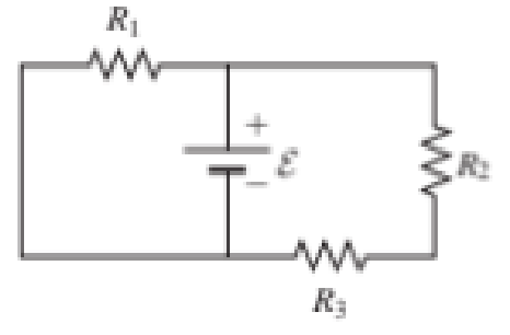
The emf in Figure P29.40 is 4.54 V. The resistances are
- a. the current in each resistor,
- b. the power consumed by each resistor, and
- c. the power supplied by the emf device.
(a)
Determine the current in each resistor.
Answer to Problem 40PQ
The current in resistor
Explanation of Solution
Refer to figure P29.40, in the given circuit,
Write the expression for current in resistor
Here,
Write the expression for current in
Here,
The current through resistance
Here,
Conclusion:
Substitute
Substitute
As the current
Therefore, the current in resistor
(b)
Power consumed by each resistor.
Answer to Problem 40PQ
Power consumed by resistor
Explanation of Solution
Write the expression for power consumed by each resistor as.
Here,
Substitute
Here,
Substitute
Here,
Substitute
Here,
Conclusion:
Substitute
Substitute
Substitute
Thus, the power consumed by resistor
(c)
Power supplied by the Emf device.
Answer to Problem 40PQ
Power supplied by the emf device is
Explanation of Solution
Write the expression for power drawn by the circuit as.
Here,
Write the expression for equivalent resistance of the given circuit as.
Substitute
Rearrange the above expression as.
Here,
Conclusion:
Substitute
Thus, the power supplied by the emf device is
Want to see more full solutions like this?
Chapter 29 Solutions
Physics for Scientists and Engineers: Foundations and Connections


- solve for (_) Narrow_forwardTwo boxes of fruit on a frictionless horizontal surface are connected by a light string as in the figure below, where m₁ = 11 kg and m₂ = 25 kg. A force of F = 80 N is applied to the 25-kg box. mq m1 Applies T Peaches i (a) Determine the acceleration of each box and the tension in the string. acceleration of m₁ acceleration of m₂ tension in the string m/s² m/s² N (b) Repeat the problem for the case where the coefficient of kinetic friction between each box and the surface is 0.10. acceleration of m₁ acceleration of m₂ tension in the string m/s² m/s2 Narrow_forwardAll correct but t1 and t2 from part Aarrow_forward
- Three long, straight wires are mounted on the vertices of an equilateral triangle as shown in the figure. The wires carry currents of I₁ = 3.50 A, I2 = 5.50 A, and I3 = 8.50 A. Each side of the triangle has a length of 34.0 cm, and the point (A) is located half way between (11) and (12) along one of the sides. Find the magnitude of the magnetic field at point (A). Solve in Teslas (T). I₁arrow_forwardNumber There are four charges, each with a magnitude of 2.38 μC. Two are positive and two are negative. The charges are fixed to the corners of a 0.132-m square, one to a corner, in such a way that the net force on any charge is directed toward the center of the square. Find the magnitude of the net electrostatic force experienced by any charge. ips que Mi Units estic re harrow_forwardTwo long, straight wires are separated by distance, d = 22.0 cm. The wires carry currents of I1 = 7.50 A and I2 = 5.50 A in opposite directions, as shown in the figure. Find the magnitude of the net magnetic field at point (B). Let r₁ = 12.0 cm, r2 = 7.00 cm, and r3 = 13.0 cm. Solve in T. 12 d A √3arrow_forward
- Thank you in advance, image with question is attached below.arrow_forwardQuestion is attached, thank you.arrow_forwardTwo very small spheres are initially neutral and separated by a distance of 0.612 m. Suppose that 4.12 × 10¹³ electrons are removed from one sphere and placed on the other. (a) What is the magnitude of the electrostatic force that acts on each sphere? (b) Is the force attractive or repulsive?arrow_forward
- Estimate the diameter of the Moon. During a total solar eclipse, the Moon passes in front of the Sun so that during “totality” their apparent sizes match and the Moon blocks light from the Sun shining on the Earth. a) What do you predict the size of the Moon would be if you were to use a pinhole in an aluminum holder, meter stick, and white paper screen to project light from the full Moon through a pinhole onto a screen that is one meter away from the pinhole? b) Describe in detail how you would use this apparatus and your knowledge of pinhole phenomena to estimate the diameter of the Moon. Assume that the distance between the Earth and the Moon is 250,000 miles.arrow_forwardThe following data was collected for a friction experiment in which an object was observed moving at constant speed over a surface. Graph the Applied Force versus the Normal Force and determine the coefficient of friction. Is this value the coefficient of kinetic friction or the coefficient of static friction? Justify your answer. Trial Normal Force Applied Force 1 4.13 1.44 2 6.41 1.68 3 8.94 2.82 4 11.34 3.94 5 13.82 5.05arrow_forward1. Measurements and Linear Regression 1.1 Introduction The objective of this lab assignment is to represent measurement data in graphical form in order to illustrate experimental data and uncertainty visually. It is often convenient to represent experimental data graphically, not only for reporting results but also to compute or measure several physical parameters. For example, consider two physical quantities represented by x and y that are linearly related according to the algebraic relationship, y=mx+b, (1.1) where m is the slope of the line and b is the y-intercept. In order to assess the linearity between y and x, it is convenient to plot these quantities in a y versus x graph, as shown in Figure 1.1. Datapoints Line of regression Figure 1.1: Best fit line example. Once the data points are plotted, it is necessary to draw a "best fit line" or "regression line" that describes the data. A best fit line is a straight line that is the best approximation of the given set of data, and…arrow_forward
 Physics for Scientists and Engineers with Modern ...PhysicsISBN:9781337553292Author:Raymond A. Serway, John W. JewettPublisher:Cengage Learning
 Physics for Scientists and Engineers: Foundations...PhysicsISBN:9781133939146Author:Katz, Debora M.Publisher:Cengage Learning
 Physics for Scientists and EngineersPhysicsISBN:9781337553278Author:Raymond A. Serway, John W. JewettPublisher:Cengage Learning
 Principles of Physics: A Calculus-Based TextPhysicsISBN:9781133104261Author:Raymond A. Serway, John W. JewettPublisher:Cengage Learning
 Physics for Scientists and Engineers, Technology ...PhysicsISBN:9781305116399Author:Raymond A. Serway, John W. JewettPublisher:Cengage Learning
 College PhysicsPhysicsISBN:9781938168000Author:Paul Peter Urone, Roger HinrichsPublisher:OpenStax College