
Concept explainers
Videos
(a)
To Show:The electric field inside a solid sphere having a charge density
(b)
The electric field at the given points 1 and 2 as shown in the figure.
Given:
The radius of the cavity is
Explanation:
Draw a diagram to show the position of the cavity.
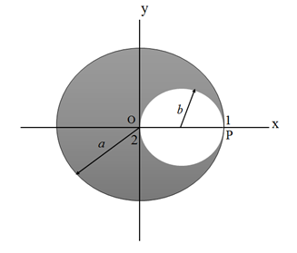
The electric field inside a cavity is equal to the sum of the electric field due to the original uncut sphere and the electric field due to the sphere of the cavity but with a uniform negative charge density.
Consider a point P at position 1.
Write the expression for the net electric field at position 1.
Here,
Substitute
The direction will be radially outward.
Take the centrepoint
Write the expression for the electric field at position 2.
Here,
Substitute 0 for
Negative sign indicates that the electric field will be towards the centre of the cavity.
Conclusion:
Thus, the electric field at point 1 is
Want to see the full answer?
Check out a sample textbook solution
Chapter 22 Solutions
PHYSICS F/SCI.+ENGRS.,STAND.-W/ACCESS


- The human eye is most sensitive to light having a frequency of about 5.5 × 10¹⁴ Hz, which is in the yellow-green region of the electromagnetic spectrum. How many wavelengths of this light can fit across a distance of 2.2 cm?arrow_forwardA one-dimensional harmonic oscillator of mass m and angular frequency w is in a heat bath of temperature T. What is the root mean square of the displacement of the oscillator? (In the expressions below k is the Boltzmann constant.) Select one: ○ (KT/mw²)1/2 ○ (KT/mw²)-1/2 ○ kT/w O (KT/mw²) 1/2In(2)arrow_forwardTwo polarizers are placed on top of each other so that their transmission axes coincide. If unpolarized light falls on the system, the transmitted intensity is lo. What is the transmitted intensity if one of the polarizers is rotated by 30 degrees? Select one: ○ 10/4 ○ 0.866 lo ○ 310/4 01/2 10/2arrow_forward
- Before attempting this problem, review Conceptual Example 7. The intensity of the light that reaches the photocell in the drawing is 160 W/m², when 0 = 18°. What would be the intensity reaching the photocell if the analyzer were removed from the setup, everything else remaining the same? Light Photocell Polarizer Insert Analyzerarrow_forwardThe lifetime of a muon in its rest frame is 2.2 microseconds. What is the lifetime of the muon measured in the laboratory frame, where the muon's kinetic energy is 53 MeV? It is known that the rest energy of the muon is 106 MeV. Select one: O 4.4 microseconds O 6.6 microseconds O 3.3 microseconds O 1.1 microsecondsarrow_forwardThe Lagrangian of a particle performing harmonic oscil- lations is written in the form L = ax² - Bx² - yx, where a, and are constants. What is the angular frequency of oscillations? A) √2/a B) √(+2a)/B C) √√Ba D) B/αarrow_forward
- The mean temperature of the Earth is T=287 K. What would the new mean temperature T' be if the mean distance between the Earth and the Sun was increased by 2%? Select one: ○ 293 K O 281 K ○ 273 K 284 Karrow_forwardTwo concentric current-carrying wire loops of radius 3 cm and 9 cm lie in the same plane. The currents in the loops flow in the same direction and are equal in magnitude. The magnetic field at the common center of the loops is 50 mT. What would be the value of magnetic field at the center if the direction of the two currents was opposite to each other (but their value is kept constant)? Select one: ○ 20 mT ○ 10 mT O 15 mT ○ 25 mTarrow_forwardAn ideal coil of inductivity 50 mH is connected in series with a resistor of 50 ohm. This system is connected to a 4.5 V battery for a long time. What is the current in the circuit? Select one: O 45 mA ○ 90 mA 00 mA O 150 mAarrow_forward
- There are two thin-walled spherical shells made from the same material, the radius of the smaller shell is half of the radius of the larger one. The thickness of the walls is the same. Denote the moment of inertia (with respect to the center) of the larger shell by I₁, and that of the smaller one by 12. What is the ratio I₁/12? Select one: ○ 8 O 16 O 4 ○ 32arrow_forwardA swimming pool has dimensions 20.0 m X 20.0 m and a flat bottom. The pool is filled to a depth of 3.00 m with fresh water. By what force does the water push each of the sidewalls? Density of water is 1000 kg/m³. Select one: ○ ~ 900 KN о ~ 2 ~ 1800 kN 600 kN 1500 kNarrow_forwardFrom one corner of a thin homogeneous square metal sheet with sides of L = 20 cm is cut an L/2 square sheet as shown in the figure. Approximately how far away is the centre of mass of the resulting shape from the centre P of the original square? P ○ 24 mm ○ 42 mm ○ 32 mm ○ 16 mmarrow_forward

 Physics for Scientists and Engineers: Foundations...PhysicsISBN:9781133939146Author:Katz, Debora M.Publisher:Cengage Learning
 Principles of Physics: A Calculus-Based TextPhysicsISBN:9781133104261Author:Raymond A. Serway, John W. JewettPublisher:Cengage Learning
 College PhysicsPhysicsISBN:9781285737027Author:Raymond A. Serway, Chris VuillePublisher:Cengage Learning
 Physics for Scientists and Engineers with Modern ...PhysicsISBN:9781337553292Author:Raymond A. Serway, John W. JewettPublisher:Cengage Learning
 Physics for Scientists and Engineers, Technology ...PhysicsISBN:9781305116399Author:Raymond A. Serway, John W. JewettPublisher:Cengage Learning