
Loose Leaf for Engineering Circuit Analysis Format: Loose-leaf
9th Edition
ISBN: 9781259989452
Author: Hayt
Publisher: Mcgraw Hill Publishers
expand_more
expand_more
format_list_bulleted
Concept explainers
Videos
Textbook Question
Chapter 2.2, Problem 5P
For the element in Fig. 2.11, v1 = 17 V. Determine v2.
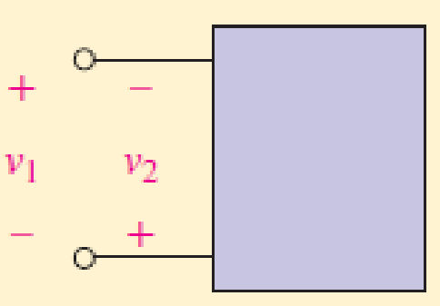
■ FIGURE 2.11
Expert Solution & Answer
Want to see the full answer?
Check out a sample textbook solution
Students have asked these similar questions
Please no AI response.
I have uploaded the rules, please explain step by step and which rule you have applied
I have uploaded the rules, please explain step by step and which rule you have applied
Chapter 2 Solutions
Loose Leaf for Engineering Circuit Analysis Format: Loose-leaf
Ch. 2.1 - A krypton fluoride laser emits light at a...Ch. 2.1 - A typical incandescent reading lamp runs at 60 W....Ch. 2.2 - In the wire of Fig. 2.7, electrons are moving left...Ch. 2.2 - For the element in Fig. 2.11, v1 = 17 V. Determine...Ch. 2.2 - Prob. 6PCh. 2.2 - Determine the power being generated by the circuit...Ch. 2.2 - Determine the power being delivered to the circuit...Ch. 2.2 - Your rechargeable smartphone battery has a voltage...Ch. 2.3 - Find the power absorbed by each element in the...Ch. 2.4 - Prob. 11P
Ch. 2.4 - Prob. 12PCh. 2.4 - The power absorbed by the resistor if i = 3 nA and...Ch. 2 - Convert the following to engineering notation: (a)...Ch. 2 - Convert the following to engineering notation:...Ch. 2 - Prob. 3ECh. 2 - Prob. 4ECh. 2 - Convert the following to SI units, taking care to...Ch. 2 - Prob. 6ECh. 2 - It takes you approximately 2 hours to finish your...Ch. 2 - A certain krypton fluoride laser generates 15 ns...Ch. 2 - Your recommended daily food intake is 2500 food...Ch. 2 - An electric vehicle is driven by a single motor...Ch. 2 - Under insolation conditions of 500 W/m2 (direct...Ch. 2 - A certain metal oxide nanowire piezoelectricity...Ch. 2 - Assuming a global population of 9 billion people,...Ch. 2 - The total charge flowing out of one end of a small...Ch. 2 - Prob. 15ECh. 2 - The total charge stored on a 1 cm diameter...Ch. 2 - A mysterious device found in a forgotten...Ch. 2 - A new type of device appears to accumulate charge...Ch. 2 - The current flowing through a tungsten-filament...Ch. 2 - The current waveform depicted in Fig. 2.28 is...Ch. 2 - The current waveform depicted in Fig. 2.29 is...Ch. 2 - A wind power system with increasing windspeed has...Ch. 2 - Two metallic terminals protrude from a device. The...Ch. 2 - The convention for voltmeters is to use a black...Ch. 2 - Determine the power absorbed by each of the...Ch. 2 - Determine the power absorbed by each of the...Ch. 2 - Determine the unknown current for the circuit in...Ch. 2 - A constant current of 1 ampere is measured flowing...Ch. 2 - Determine the power supplied by the leftmost...Ch. 2 - The currentvoltage characteristic of a silicon...Ch. 2 - A particular electric utility charges customers...Ch. 2 - The Tilting Windmill Electrical Cooperative LLC...Ch. 2 - A laptop computer consumes an average power of 20...Ch. 2 - You have just installed a rooftop solar...Ch. 2 - Prob. 35ECh. 2 - Some of the ideal sources in the circuit of Fig....Ch. 2 - Prob. 37ECh. 2 - Refer to the circuit represented in Fig. 2.35,...Ch. 2 - Prob. 39ECh. 2 - Prob. 40ECh. 2 - Prob. 41ECh. 2 - Determine the magnitude of the current flowing...Ch. 2 - Real resistors can only be manufactured to a...Ch. 2 - (a) Sketch the current-voltage relationship...Ch. 2 - Prob. 45ECh. 2 - Figure 2.38 depicts the currentvoltage...Ch. 2 - Examine the I-V characteristics in Fig. 2.38....Ch. 2 - Determine the conductance (in siemens) of the...Ch. 2 - Determine the magnitude of the current flowing...Ch. 2 - A 1% tolerance 1 k resistor may in reality have a...Ch. 2 - Utilize the fact that in the circuit of Fig. 2.39,...Ch. 2 - For the circuit in Fig. 2.39, suppose that the...Ch. 2 - For each of the circuits in Fig. 2.40, find the...Ch. 2 - Sketch the power absorbed by a 100 resistor as a...Ch. 2 - You built an android that has a subcircuit...Ch. 2 - Using the data in Table 2.4, calculate the...Ch. 2 - Prob. 58ECh. 2 - Prob. 59ECh. 2 - Prob. 60ECh. 2 - The resistance values in Table 2.4 are calibrated...Ch. 2 - Prob. 62ECh. 2 - Prob. 63ECh. 2 - The network shown in Fig. 2.42 can be used to...Ch. 2 - Prob. 65ECh. 2 - An LED operates at a current of 40 mA, with a...Ch. 2 - You have found a way to directly power your wall...
Knowledge Booster


Learn more about
Need a deep-dive on the concept behind this application? Look no further. Learn more about this topic, electrical-engineering and related others by exploring similar questions and additional content below.Similar questions
- I have uploaded the rules, please explain step by step and which rule you have appliedarrow_forwardUsing the CCS Compiler method to solve this question Write a PIC16F877A program that flash ON the 8-LED's connected to port-B by using two switches connected to port-D (Do & D₁) as shown in figure below, according to the following scenarios: (Hint: Use 500ms delay for each case with 4MHz frequency) 1. When Do=1 then B₁,B3,B7 are ON. 2. When Do 0 then Bo,B2, B4, B5, B6 are ON. 3. When D₁=1 then B4,B,,B6,B7 are ON. 4. When D₁-0 then Bo,B1,B2,B3 are ON.arrow_forwardUse the ramp generator circuit in Fig. B2a to generate the waveform shown in Fig. B2b. Write four equations relating resistors R1, R2, R3, capacitor C and voltages Vs, VR and VA.to the waveform parameters T₁, T, Vcm and Vm- If R = R2 = R3, R₁ = 2R, C = 1 nF, Vcm = 2 V and Vm = 1 V, T₁ = 2 μs and T = 10 μs solve for the values of R, Vs, VR and VA using your equations from part a(i). VR C +VA R3 V₂ Vo мат R1 VsO+ V₁ R₂ Figure B2a Vout Vcm+Vm Vcm Vcm-Vm 0 T₁ T 2T time Figure B2barrow_forward
- The circuit in Figure B1a is a common analogue circuit block. Explain why you would need such a circuit. Draw another circuit in which you use the current flowing in this loop to bias a common source amplifier. This circuit is not ideal for standard CMOS technologies due to threshold shift. Why? Draw an improved version of this circuit to make it better. VDD (W)P MA M3. (), REF (쁜)~ M₁ M2 lout 시~ Rsarrow_forward23bcarrow_forwardDraw the small-signal equivalent circuit of a single transistor amplifier given in figure B1b. Assume the current source to be ideal. Determine the Open-loop transfer function, pole frequency and gain-bandwidth product all in terms of transistor parameters 9m, To and CL. If the load capacitance is 1pF and the necessary unity gain frequency is 600MHz, find the gm for this transistor. V₁ V₁ CLarrow_forward
arrow_back_ios
SEE MORE QUESTIONS
arrow_forward_ios
Recommended textbooks for you
 Introductory Circuit Analysis (13th Edition)Electrical EngineeringISBN:9780133923605Author:Robert L. BoylestadPublisher:PEARSON
 Delmar's Standard Textbook Of ElectricityElectrical EngineeringISBN:9781337900348Author:Stephen L. HermanPublisher:Cengage Learning
 Programmable Logic ControllersElectrical EngineeringISBN:9780073373843Author:Frank D. PetruzellaPublisher:McGraw-Hill Education
 Fundamentals of Electric CircuitsElectrical EngineeringISBN:9780078028229Author:Charles K Alexander, Matthew SadikuPublisher:McGraw-Hill Education
 Electric Circuits. (11th Edition)Electrical EngineeringISBN:9780134746968Author:James W. Nilsson, Susan RiedelPublisher:PEARSON
 Engineering ElectromagneticsElectrical EngineeringISBN:9780078028151Author:Hayt, William H. (william Hart), Jr, BUCK, John A.Publisher:Mcgraw-hill Education,
Introductory Circuit Analysis (13th Edition)
Electrical Engineering
ISBN:9780133923605
Author:Robert L. Boylestad
Publisher:PEARSON
Delmar's Standard Textbook Of Electricity
Electrical Engineering
ISBN:9781337900348
Author:Stephen L. Herman
Publisher:Cengage Learning
Programmable Logic Controllers
Electrical Engineering
ISBN:9780073373843
Author:Frank D. Petruzella
Publisher:McGraw-Hill Education
Fundamentals of Electric Circuits
Electrical Engineering
ISBN:9780078028229
Author:Charles K Alexander, Matthew Sadiku
Publisher:McGraw-Hill Education
Electric Circuits. (11th Edition)
Electrical Engineering
ISBN:9780134746968
Author:James W. Nilsson, Susan Riedel
Publisher:PEARSON
Engineering Electromagnetics
Electrical Engineering
ISBN:9780078028151
Author:Hayt, William H. (william Hart), Jr, BUCK, John A.
Publisher:Mcgraw-hill Education,
Photoelectric Effect, Work Function, Threshold Frequency, Wavelength, Speed & Kinetic Energy, Electr; Author: The Organic Chemistry Tutor;https://www.youtube.com/watch?v=-LECEvusk8E;License: Standard Youtube License