
Loose Leaf for Engineering Circuit Analysis Format: Loose-leaf
9th Edition
ISBN: 9781259989452
Author: Hayt
Publisher: Mcgraw Hill Publishers
expand_more
expand_more
format_list_bulleted
Concept explainers
Videos
Textbook Question
Chapter 2, Problem 47E
Examine the I-V characteristics in Fig. 2.38. Which would be the most desirable for a fuse? Explain.
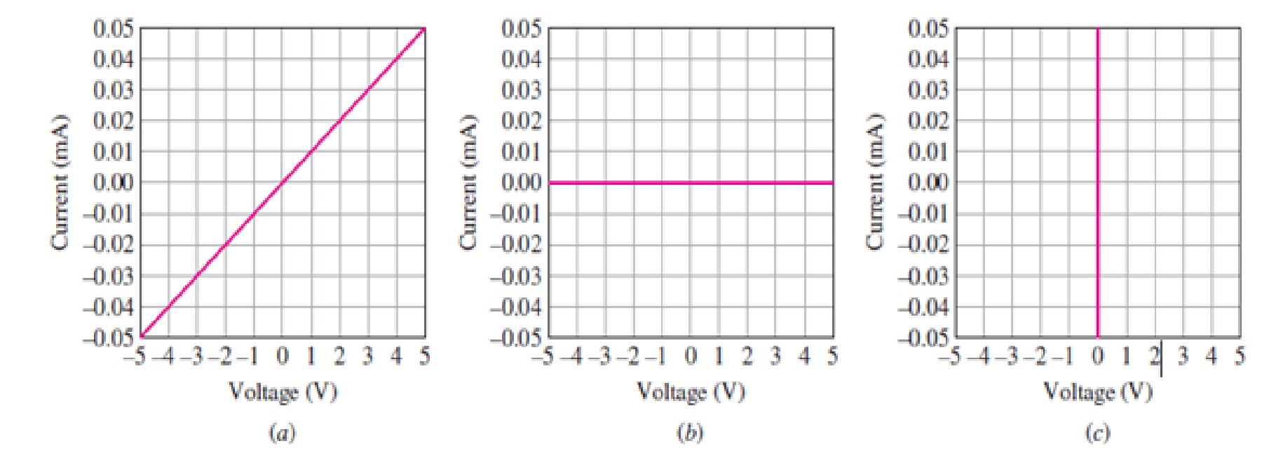
FIGURE 2.38
Expert Solution & Answer
Want to see the full answer?
Check out a sample textbook solution
Students have asked these similar questions
Design a full-wave rectifier power supply using a 9.52:1 transformer. Assume that the outlet is120 V rms @ 60 Hz. Further assume that the diode turn-on voltage V D(on) is 0.7 V. Pick the valueof CL such that vo has a maximum ripple of 1 V p-p . Solve for the average value of vo = Vo (notethat this may be greater than 12 V) and iD(ave) = ID.
Light-emitting diodes (LEDs) are diodes made with III-V compound semiconductor materials such as aluminum gallium arsenide (AlGaAs), aluminum indium gallium phosphide (AlInGaP) or indium gallium nitride (InGaN), instead of silicon. The LEDs emit light when the device is operated under forward bias. LEDs of different colors have different turn-on voltages VD(on). For example:
VD(on) :
Red: ~ 1.6 V
Yellow: ~ 1.7 V
Green: ~ 1.8 V
Blue: ~ 2.8 V
White: ~ 3.8 V
(a) Model these five LEDs with a simplified piecewise linear model
(b) A rule of thumb is that it takes about 1 mA of current to “light” an LED while ~ 10 mA is needed for it to appear bright. Use the piecewise linear model for the LEDs, for the over-voltage indicator circuit to the right, find the values of Vin which will cause D1 or D2 to light (i.e. when ID1 or ID2 exceeds 1 mA).
Consider a fixed and updated instrumentation amplifier (where two resistors are lumped into one
resistor), analyze the circuit if a common voltage source (VICM) is connected to two inputs.
A₁
R₂
+
R₁
R₂,
RA
www
www
R₁
R₁
www
A3
X
R₁
R₂
www
www
R₁₂
+
Vo
RA
A2
V2 O-
+
R₂
12
R₁
Chapter 2 Solutions
Loose Leaf for Engineering Circuit Analysis Format: Loose-leaf
Ch. 2.1 - A krypton fluoride laser emits light at a...Ch. 2.1 - A typical incandescent reading lamp runs at 60 W....Ch. 2.2 - In the wire of Fig. 2.7, electrons are moving left...Ch. 2.2 - For the element in Fig. 2.11, v1 = 17 V. Determine...Ch. 2.2 - Prob. 6PCh. 2.2 - Determine the power being generated by the circuit...Ch. 2.2 - Determine the power being delivered to the circuit...Ch. 2.2 - Your rechargeable smartphone battery has a voltage...Ch. 2.3 - Find the power absorbed by each element in the...Ch. 2.4 - Prob. 11P
Ch. 2.4 - Prob. 12PCh. 2.4 - The power absorbed by the resistor if i = 3 nA and...Ch. 2 - Convert the following to engineering notation: (a)...Ch. 2 - Convert the following to engineering notation:...Ch. 2 - Prob. 3ECh. 2 - Prob. 4ECh. 2 - Convert the following to SI units, taking care to...Ch. 2 - Prob. 6ECh. 2 - It takes you approximately 2 hours to finish your...Ch. 2 - A certain krypton fluoride laser generates 15 ns...Ch. 2 - Your recommended daily food intake is 2500 food...Ch. 2 - An electric vehicle is driven by a single motor...Ch. 2 - Under insolation conditions of 500 W/m2 (direct...Ch. 2 - A certain metal oxide nanowire piezoelectricity...Ch. 2 - Assuming a global population of 9 billion people,...Ch. 2 - The total charge flowing out of one end of a small...Ch. 2 - Prob. 15ECh. 2 - The total charge stored on a 1 cm diameter...Ch. 2 - A mysterious device found in a forgotten...Ch. 2 - A new type of device appears to accumulate charge...Ch. 2 - The current flowing through a tungsten-filament...Ch. 2 - The current waveform depicted in Fig. 2.28 is...Ch. 2 - The current waveform depicted in Fig. 2.29 is...Ch. 2 - A wind power system with increasing windspeed has...Ch. 2 - Two metallic terminals protrude from a device. The...Ch. 2 - The convention for voltmeters is to use a black...Ch. 2 - Determine the power absorbed by each of the...Ch. 2 - Determine the power absorbed by each of the...Ch. 2 - Determine the unknown current for the circuit in...Ch. 2 - A constant current of 1 ampere is measured flowing...Ch. 2 - Determine the power supplied by the leftmost...Ch. 2 - The currentvoltage characteristic of a silicon...Ch. 2 - A particular electric utility charges customers...Ch. 2 - The Tilting Windmill Electrical Cooperative LLC...Ch. 2 - A laptop computer consumes an average power of 20...Ch. 2 - You have just installed a rooftop solar...Ch. 2 - Prob. 35ECh. 2 - Some of the ideal sources in the circuit of Fig....Ch. 2 - Prob. 37ECh. 2 - Refer to the circuit represented in Fig. 2.35,...Ch. 2 - Prob. 39ECh. 2 - Prob. 40ECh. 2 - Prob. 41ECh. 2 - Determine the magnitude of the current flowing...Ch. 2 - Real resistors can only be manufactured to a...Ch. 2 - (a) Sketch the current-voltage relationship...Ch. 2 - Prob. 45ECh. 2 - Figure 2.38 depicts the currentvoltage...Ch. 2 - Examine the I-V characteristics in Fig. 2.38....Ch. 2 - Determine the conductance (in siemens) of the...Ch. 2 - Determine the magnitude of the current flowing...Ch. 2 - A 1% tolerance 1 k resistor may in reality have a...Ch. 2 - Utilize the fact that in the circuit of Fig. 2.39,...Ch. 2 - For the circuit in Fig. 2.39, suppose that the...Ch. 2 - For each of the circuits in Fig. 2.40, find the...Ch. 2 - Sketch the power absorbed by a 100 resistor as a...Ch. 2 - You built an android that has a subcircuit...Ch. 2 - Using the data in Table 2.4, calculate the...Ch. 2 - Prob. 58ECh. 2 - Prob. 59ECh. 2 - Prob. 60ECh. 2 - The resistance values in Table 2.4 are calibrated...Ch. 2 - Prob. 62ECh. 2 - Prob. 63ECh. 2 - The network shown in Fig. 2.42 can be used to...Ch. 2 - Prob. 65ECh. 2 - An LED operates at a current of 40 mA, with a...Ch. 2 - You have found a way to directly power your wall...
Knowledge Booster


Learn more about
Need a deep-dive on the concept behind this application? Look no further. Learn more about this topic, electrical-engineering and related others by exploring similar questions and additional content below.Similar questions
- Show that the input impedance of a lossy transmission line of length L connected to a load impedance of Z is given by Z₁Cosh(yL) + ZoSinh(yL) Zin = Zo ZoCosh(YL) + Z₁Sihh(YL) ex Where Cosh(x) = and Sinh(x) = are the hyperbolic cosine and sine, respectively. 2 2arrow_forwardA sinusoidal source of V = 10 and Z = 50 - j40 is connected to a 60 lossless transmission line of length 100 m with ẞ = 0.25. What is the Thevenin's equivalent of this system seen looking into the load end of the transmission line?arrow_forward2. On a distortionless transmission line, the voltage wave is given by v(L,t) = 110e0.005L Cos(10³t + 2L) +55e-0.005L Cos(108t-2L) where L is the length of the transmission line as measured from the load. If Z = 30002, find a,ẞ, vp, and Zo.arrow_forward
- A 50 transmission line is to be connected to a 72 load through a 1/4 quarter wave matching transformer. (a) What must be the characteristic impedance of the transmission line that is used to form the quarter wave transformer? (b) If the frequency of operation is 7 MHz and the phase velocity through the quarter wave section is 2c/3, what is the length of the quarter wave section? You may assume the transmission line forming the quarter wave section is lossless.arrow_forwardWhat is the SWR on a transmission line if the forward power arriving at the load is 5W but only 4.6W is dissipated by the load?arrow_forwardPlease do not send the AI solution as it is full of errors. Solve the question yourself, please. Q- If you have a unipolar winding stepper motor, draw the driver and the control circuit. In subject (A stepper motor driver circuit and direction control using Arduino microcontroller)arrow_forward
- 1- Draw the complete circuit diagram that illustrates the experiment concept as in figure 5 by showing the pins number. Show the following in your plot (Arduino board, steppermotor coils and the driver circuit). Note: The drawing should be on paper and not with artificial intelligence, please.arrow_forwardIn the circuit shown, find the following: 1) The current Ix. 2) The average power dissipated in the capacitor. 3) The total average power dissipated in the two resistors. 4) The average power of the independent voltage source and specify whether it is supplied or absorbed. 5) The total impedance seen from the terminals of the independent voltage source (Z=V/I). 20 -201 12/00V(+ 21 www 202arrow_forward2- If you have a unipolar winding stepper motor, draw the driver and the control circuit. Note: The drawing is on paper.arrow_forward
- Given the following reaction system, where Xo is the input, i.e u(t) = k₁ × Xo: $Xo -> x1; k1*Xo x2; k2*x1 x1 2 x2 ->%; k3*x2^2 x2 ->; k4*x2 Xo 1; k1 = 0.4 k2 4.5; k3 = 0.75 k4= 0.2 a) Build the model in Tellurium and run a simulation. Compute the Jacobian at steady state using the method getFull Jacobian(). Make sure you are at steady state! b) Write out the values for n and p c) Write out the differential equations. d) Write out the state space representation in terms of the rate constants etc. e) Compute the values in the Jacobian matrix from d) by substituting the values of the rate constants etc and any data you need from the simulation. f) Confirm that the Jacobian you get in e) is the same as the one computed from the simulation in a). g) Is the system stable or not? If you find an eigenvalue of zero, that means the system is marginally stable. You can get the eigenvalues using the tellurium method r.getFullEigenvalues()arrow_forwardSolve by Pen and Paper not using chatgpt or AIarrow_forwardYou just got a job at Shin-Etsu Chemical growing Si crystals with different dopants. Howmuch Ga needs to be added to 800 kg of Si melt to achieve a 5-10 Ω.cm (measured at midheight) Si CZ crystal with the following characteristics: height: 7 ft, width: 12 inchesdiameter. Assume, angular rotation 10 RPM, melt viscosity 0.1 poise, pull velocity 2mm/min.a. Generate a plot of the doping distribution throughout the length of the crystal (CGa vs. fs ).b. If a second crystal were to be pulled out of the melt without replenishment of silicon nordopant what would be the average resistivity of this crystal (or resistivity at mid height)arrow_forward
arrow_back_ios
SEE MORE QUESTIONS
arrow_forward_ios
Recommended textbooks for you
 Introductory Circuit Analysis (13th Edition)Electrical EngineeringISBN:9780133923605Author:Robert L. BoylestadPublisher:PEARSON
 Delmar's Standard Textbook Of ElectricityElectrical EngineeringISBN:9781337900348Author:Stephen L. HermanPublisher:Cengage Learning
 Programmable Logic ControllersElectrical EngineeringISBN:9780073373843Author:Frank D. PetruzellaPublisher:McGraw-Hill Education
 Fundamentals of Electric CircuitsElectrical EngineeringISBN:9780078028229Author:Charles K Alexander, Matthew SadikuPublisher:McGraw-Hill Education
 Electric Circuits. (11th Edition)Electrical EngineeringISBN:9780134746968Author:James W. Nilsson, Susan RiedelPublisher:PEARSON
 Engineering ElectromagneticsElectrical EngineeringISBN:9780078028151Author:Hayt, William H. (william Hart), Jr, BUCK, John A.Publisher:Mcgraw-hill Education,
Introductory Circuit Analysis (13th Edition)
Electrical Engineering
ISBN:9780133923605
Author:Robert L. Boylestad
Publisher:PEARSON
Delmar's Standard Textbook Of Electricity
Electrical Engineering
ISBN:9781337900348
Author:Stephen L. Herman
Publisher:Cengage Learning
Programmable Logic Controllers
Electrical Engineering
ISBN:9780073373843
Author:Frank D. Petruzella
Publisher:McGraw-Hill Education
Fundamentals of Electric Circuits
Electrical Engineering
ISBN:9780078028229
Author:Charles K Alexander, Matthew Sadiku
Publisher:McGraw-Hill Education
Electric Circuits. (11th Edition)
Electrical Engineering
ISBN:9780134746968
Author:James W. Nilsson, Susan Riedel
Publisher:PEARSON
Engineering Electromagnetics
Electrical Engineering
ISBN:9780078028151
Author:Hayt, William H. (william Hart), Jr, BUCK, John A.
Publisher:Mcgraw-hill Education,
How Do Hall Effect Sensors Work? - The Learning Circuit; Author: element14 presents;https://www.youtube.com/watch?v=dgyB2-1VDI0;License: Standard Youtube License