
Loose Leaf for Engineering Circuit Analysis Format: Loose-leaf
9th Edition
ISBN: 9781259989452
Author: Hayt
Publisher: Mcgraw Hill Publishers
expand_more
expand_more
format_list_bulleted
Concept explainers
Videos
Textbook Question
Chapter 2, Problem 53E
For the circuit in Fig. 2.39, suppose that the resistor R2 represents a very sensitive and expensive piece of electronics. To ensure that the equipment is not damaged, R1 is incorporated to represent a fuse, with a rating of 5 A and resistance of 0.1 Ω. If the voltage source is 12 V, what is the lowest resistance that could be encountered as a short circuit condition for R2 before blowing the fuse?
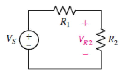
■ FIGURE 2.39
Expert Solution & Answer
Want to see the full answer?
Check out a sample textbook solution
Students have asked these similar questions
In Fig.35 resistive loads, 1, 2, and 3, respectively, absorb 1200 W, 2400 W, and 3600 W. Calculate the current:
a. In lines A and B.
b. In the neutral conductors.
c. In the HV line.
+
-ww
I
2
12V
2
Determine I, I,, I₂ and V₁
1 _< +
www
5 12
16
6
5
www
Determine (a) the average and (b) rms values of the periodiccurrent waveform shown in Fig. P8.9
Chapter 2 Solutions
Loose Leaf for Engineering Circuit Analysis Format: Loose-leaf
Ch. 2.1 - A krypton fluoride laser emits light at a...Ch. 2.1 - A typical incandescent reading lamp runs at 60 W....Ch. 2.2 - In the wire of Fig. 2.7, electrons are moving left...Ch. 2.2 - For the element in Fig. 2.11, v1 = 17 V. Determine...Ch. 2.2 - Prob. 6PCh. 2.2 - Determine the power being generated by the circuit...Ch. 2.2 - Determine the power being delivered to the circuit...Ch. 2.2 - Your rechargeable smartphone battery has a voltage...Ch. 2.3 - Find the power absorbed by each element in the...Ch. 2.4 - Prob. 11P
Ch. 2.4 - Prob. 12PCh. 2.4 - The power absorbed by the resistor if i = 3 nA and...Ch. 2 - Convert the following to engineering notation: (a)...Ch. 2 - Convert the following to engineering notation:...Ch. 2 - Prob. 3ECh. 2 - Prob. 4ECh. 2 - Convert the following to SI units, taking care to...Ch. 2 - Prob. 6ECh. 2 - It takes you approximately 2 hours to finish your...Ch. 2 - A certain krypton fluoride laser generates 15 ns...Ch. 2 - Your recommended daily food intake is 2500 food...Ch. 2 - An electric vehicle is driven by a single motor...Ch. 2 - Under insolation conditions of 500 W/m2 (direct...Ch. 2 - A certain metal oxide nanowire piezoelectricity...Ch. 2 - Assuming a global population of 9 billion people,...Ch. 2 - The total charge flowing out of one end of a small...Ch. 2 - Prob. 15ECh. 2 - The total charge stored on a 1 cm diameter...Ch. 2 - A mysterious device found in a forgotten...Ch. 2 - A new type of device appears to accumulate charge...Ch. 2 - The current flowing through a tungsten-filament...Ch. 2 - The current waveform depicted in Fig. 2.28 is...Ch. 2 - The current waveform depicted in Fig. 2.29 is...Ch. 2 - A wind power system with increasing windspeed has...Ch. 2 - Two metallic terminals protrude from a device. The...Ch. 2 - The convention for voltmeters is to use a black...Ch. 2 - Determine the power absorbed by each of the...Ch. 2 - Determine the power absorbed by each of the...Ch. 2 - Determine the unknown current for the circuit in...Ch. 2 - A constant current of 1 ampere is measured flowing...Ch. 2 - Determine the power supplied by the leftmost...Ch. 2 - The currentvoltage characteristic of a silicon...Ch. 2 - A particular electric utility charges customers...Ch. 2 - The Tilting Windmill Electrical Cooperative LLC...Ch. 2 - A laptop computer consumes an average power of 20...Ch. 2 - You have just installed a rooftop solar...Ch. 2 - Prob. 35ECh. 2 - Some of the ideal sources in the circuit of Fig....Ch. 2 - Prob. 37ECh. 2 - Refer to the circuit represented in Fig. 2.35,...Ch. 2 - Prob. 39ECh. 2 - Prob. 40ECh. 2 - Prob. 41ECh. 2 - Determine the magnitude of the current flowing...Ch. 2 - Real resistors can only be manufactured to a...Ch. 2 - (a) Sketch the current-voltage relationship...Ch. 2 - Prob. 45ECh. 2 - Figure 2.38 depicts the currentvoltage...Ch. 2 - Examine the I-V characteristics in Fig. 2.38....Ch. 2 - Determine the conductance (in siemens) of the...Ch. 2 - Determine the magnitude of the current flowing...Ch. 2 - A 1% tolerance 1 k resistor may in reality have a...Ch. 2 - Utilize the fact that in the circuit of Fig. 2.39,...Ch. 2 - For the circuit in Fig. 2.39, suppose that the...Ch. 2 - For each of the circuits in Fig. 2.40, find the...Ch. 2 - Sketch the power absorbed by a 100 resistor as a...Ch. 2 - You built an android that has a subcircuit...Ch. 2 - Using the data in Table 2.4, calculate the...Ch. 2 - Prob. 58ECh. 2 - Prob. 59ECh. 2 - Prob. 60ECh. 2 - The resistance values in Table 2.4 are calibrated...Ch. 2 - Prob. 62ECh. 2 - Prob. 63ECh. 2 - The network shown in Fig. 2.42 can be used to...Ch. 2 - Prob. 65ECh. 2 - An LED operates at a current of 40 mA, with a...Ch. 2 - You have found a way to directly power your wall...
Knowledge Booster


Learn more about
Need a deep-dive on the concept behind this application? Look no further. Learn more about this topic, electrical-engineering and related others by exploring similar questions and additional content below.Similar questions
- Repairs have to be carried out on HV cir- cuit breaker No. 6 shown in Fig. 26. If the three 220 kV lines must be kept in service, which disconnecting switches must be kept open?arrow_forwardFind the voltage v(t) for t>=0 show all steps and redraw circuit as necessary, the switch closes at t=0 and v(t) is the voltage over the 4ohm resistor as shown in the circuit.arrow_forwardFind the voltage v(t) for t>=0 please redraw circuit as necessary and show all steps.arrow_forward
- Determine (a) the average and (b) rms values of the periodiccurrent waveform shown in Fig. P8.9arrow_forwardFind Eigenvalues and Eigenvectors for the following matrices: [5 -6 1 A = 1 1 0 3 0 1arrow_forwardUse Gauss-Jordan Elimination method to solve the following system: 4x1+5x2 + x3 = 2 x1-2x2-3x3 = 7 3x1 x2 2x3 = 1. -arrow_forward
- 3. As the audio frequency of Fig. 11-7 goes down, what components of Fig. 12-4 must be modified for normal operation? OD C₂ 100 HF R₁ 300 Re 300 ww 100A R 8 Voc Rz 10k reset output 3 R7 8 Voc 3 reset output Z discharge VR₁ 5k 2 trigger 2 trigger 7 discharge R 3 1k 5 control voltage threshold 6 5 control voltage 6 threshold GND Rs 2k C. C. 100 GND Uz LM555 1 Ce 0.01 U, LM555 0.01 8.01.4 PRO Fig. 11-7 Audio lutput Pulse width modulator R4 1k ww C7 Re 1k ww R7 100 VR 50k 10μ Ra R10 C₁. R1 3.9k 3.9k 0.14 100k TO w Rs 51 82 3 H 10 Carrier U₁ Ca Input A741 2.2 Us MC1496 PWM signal input R2 0.1100k Uz A741 41 Cs 1 Re 10k VR2 50k VR3 100k 14 12 C3. 3% + Ce 0.1 10μ 5 1A HH C +12V 0.1 O PWM Output C 0.02- R 100k +12 V Demodulated output 6 Ca 0.33 w R 10k R12 100k ww 31 о + 4A741 -12 V Fig. 12-4 PWM demodulator C 1500parrow_forwardDUC 1. In Fig. 12-4, what are the functions of the VR1 and VR2? 2. In Fig. 12-4, what is the function of the VR3? VR₁ 50k C₁ R1 0.1 100k Carrier Input U₁ A741 PWM signal input R41k www Re 1k w C7 ± 10μT R7 100 ww =L H C4 2.2 H W82 Rs 51 3 10 U3 MC1496 C2 R2 U2 A741 22 0.1 100k VR2 50k VR3 100kr 14 C3 10μ 1k 0.1 4 5 6 12 m Re 10k R9 R102 3.9k 3.9k HHI C10 0.1 -0 +12V C11 R 0.02 100k +12 V Demodulated output C R11 R12 A741 0.33 10k 100k -12 V Ca 1μ C12 1500p PRODUC Fig. 12-4 PWM demodulator PRODUCTSarrow_forward10.37 Use mesh analysis to find currents I₁, I2, and I3 in the circuit of Fig. 10.82. ML 120-90° V 120 -30° V Figure 10.82 For Prob. 10.37. N N Z=80-135arrow_forward
- 3. Find the phasor current I。 in the circuit shown below. Be aware of the direction markings. (15 pts) 1052 I 5057 ①520 Amps 2012 j5052arrow_forward10.93 Figure 10.135 shows a Colpitts oscillator. Show that the ed oscillation frequency is 1 fo= 2π √√LCT where CTC₁C2/(C₁ + C₂). Assume R; >>> R₁ + Rf ww Vo L m C₂ C₁ 5 Xci Figure 10.135 A Colpitts oscillator; for Prob. 10.93. (Hint: Set the imaginary part of the impedance in the feedback circuit equal to zero.)arrow_forwardDetermine (a) the average and (b) rms values of the periodiccurrent waveform shown in Fig. P8.3.arrow_forward
arrow_back_ios
SEE MORE QUESTIONS
arrow_forward_ios
Recommended textbooks for you
 EBK ELECTRICAL WIRING RESIDENTIALElectrical EngineeringISBN:9781337516549Author:SimmonsPublisher:CENGAGE LEARNING - CONSIGNMENT
EBK ELECTRICAL WIRING RESIDENTIAL
Electrical Engineering
ISBN:9781337516549
Author:Simmons
Publisher:CENGAGE LEARNING - CONSIGNMENT
Photoelectric Effect, Work Function, Threshold Frequency, Wavelength, Speed & Kinetic Energy, Electr; Author: The Organic Chemistry Tutor;https://www.youtube.com/watch?v=-LECEvusk8E;License: Standard Youtube License