
Concept explainers
Videos
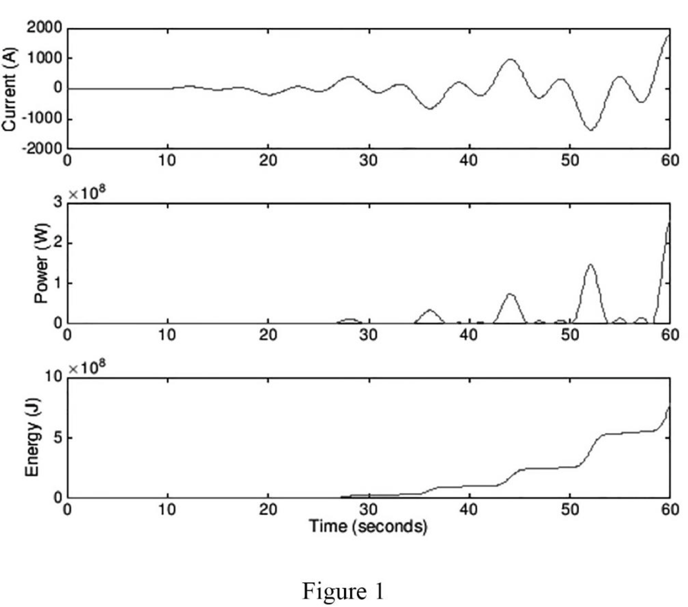
A wind power system with increasing windspeed has the current waveform described by the equation below, delivered to an 80 Ω resistor. Plot the current, power, and energy waveform over a period of 60 s, and calculate the total energy collected over the 60 s time period.
Sketch the current, power, and energy waveform over a period of 60 s to the current waveform of the wind power system. Also calculate the total energy collected over the 60 s time period.
Answer to Problem 22E
The plot for the current, power, and energy waveform is sketched as shown in Figure 1, and the total energy collected over the 60 s time period is
Explanation of Solution
Given data:
The current waveform is,
The resistor is
Formula used:
Write the general expression to find the power as follows,
Write the general expression to find the energy as follows,
Calculation:
Substitute the value of
Applying equation (3) in equation (2) as follows,
Consider the function,
Consider
Substituting the values in equation (5) as follows,
Consider,
Applying the product to sum formulas in the above expression as follows,
Consider,
By applying integration by parts in the above expression,
Applying the values in equation (8) as follows,
Consider the function,
Solving,
By applying integration by parts in the above expression,
Applying the values in the above equation as follows,
Consider,
Solving,
By applying integration by parts in the above expression,
Applying the values in the above equation as follows,
Consider,
Solving,
By applying integration by parts in the above expression,
Applying the values in the above equation as follows,
Consider,
Let,
Applying the values in the above expression,
Substituting the values in equation (13) as follows,
Substitute the above value in the considered expression
Substitute the above value in equation (12) as follows,
Substitute the above value in equation (11) as follows,
Substitute the above value in equation (10) as follows,
Substitute the above value in equation (9) as follows,
Consider the function
Applying integration by parts in the above expression,
Applying the values in the above equation as follows,
Consider,
Let,
Applying integration by parts in the above expression,
Applying the values in the above equation as follows,
Consider,
Let,
Applying integration by parts in the above expression,
Applying the values in the above equation as follows,
Consider,
Let,
Applying integration by parts in the above expression,
Applying the values in the above equation as follows,
Consider,
Let,
Substituting the values,
Substitute the above value in equation (22) as follows,
Substitute the above value in equation (21) as follows,
Substitute the above value in equation (20) as follows,
Substitute the above value in equation (18) as follows
Substitute the above value in equation (17) as follows
Substitute the above value in equation (16) as follows
Substitute the above value in equation (15) as follows
Consider the function
Applying integration by parts in the above expression,
Applying the values in the above equation as follows,
Consider,
Let,
Applying integration by parts in the above expression,
Applying the values in the above equation as follows,
Consider,
Let,
Applying integration by parts in the above expression,
Applying the values in the above equation as follows,
Consider,
Let,
Applying integration by parts in the above expression,
Applying the values in the above equation as follows,
Consider,
Let,
Applying the values in the above equation as follows,
Substitute the above value in equation (33) as follows,
Substitute the above value in equation (31) as follows,
Substitute the above value in equation (30) as follows,
Substitute the above value in equation (29) as follows,
Substitute the above value in equation (28) as follows,
Substitute the above value in equation (26) as follows,
Substitute the above value in equation (25) as follows,
Consider the function
Substitute the calculated values of equation (34), (35), (23), and (14) in the expression x as follows,
Substitute the above value in equation (6) as follows,
Substitute
Applying the limits to the above expression over a period of 60 s,
Matlab code to plot for wind power waveform:
t_end = 60; % End time in seconds
t_pts = 600; % Number of points for time vector
t=linspace(0,t_end,t_pts); % Define time vector
dt=t_end/t_pts; % Separation between time points
R=80; % Resistance in ohms
for i=1:t_pts; % Iterate for each point in time
current(i)=0.5*t(i)^2*sin(pi/8*t(i))*cos(pi/4*t(i));
p(i)=current(i)^2*R;
end
w=cumsum(p)*dt; % Energy from cumulative sum times time separation
figure(1)
subplot(3,1,1); plot(t,current,'r'); % Plot voltage
ylabel('Current (A)');
subplot(3,1,2); plot(t,p,'r') % Plot power
ylabel('Power (W)')
subplot(3,1,3); plot(t,w,'r') % Plot energy
xlabel('Time (seconds)')
ylabel('Energy (J)')
Matlab output:
Figure 1 shows the plot for the current, power, and energy waveform.
Conclusion:
Thus, the plot for the current, power, and energy waveform is sketched as shown in Figure 1, and the total energy collected over the 60 s time period is
Want to see more full solutions like this?
Chapter 2 Solutions
Loose Leaf for Engineering Circuit Analysis Format: Loose-leaf


- Select a short-circuit withstanding (1-second short circuit length) cable for Feeder 1 in Figure 1. Values for cables are given in Table 1. The voltage of the supplying network is now 115 kV and the short-circuit power of the supplying network is 2000 MVA. Table 1. Technical information of 3-phase cables (10 kV and 20 kV) Product's name EA-number Structural information 20KV 20KV 20 KV 0624250 0624252 0624253 0624254 AHKAMK-W AHKAMKW AHKAMKWAHKAMKW AHKAMKW AHKAMKW AHKAMKW 3x50Al+35Cu 3x95 Al. 35Cu 3x120Al. 35Cu 3x150Al+35Cu 3x185Al+35Cu 3x240A1+70 Cu 3x300Al+70Cu 20kV 20kV 20 kV (8) 20KV 0624255 0624257 0624256 Diameter of conductor Diameter of out-most circle Cable's outer diameter Mass Delivery information Standard length Delivery reel mm 8.0 11.3 12.7 14.1 15.7 18.1 20.3 mm 28 32 34 35 37 40 43 mm 64 71 74 76 80 89 94 aluminium kg/km 510 910 1100 1350 1650 2200 2700 сорраг kg/km 305 305 305 305 305 600 600 cable kg/km 2350 3100 3450 3800 4300 5500 6250 E 500 500 500 500 500 500 500…arrow_forwardA three-phase 20 kV medium-voltage line is 10 km. Resistance is 0.252 2/km and reactance is 0.128 92/km (inductive). Voltage at the beginning of line is 21.0 kV. At the end of the line is loading P = 2.5 MW with power factor 0.92ind. Draw 1-phase equivalent diagram and calculate line voltage at the end the of line, active and reactive power at the beginning of the line and power losses of the line.arrow_forwardA three-phase 20 kV medium-voltage line is 10 km. Resistance is 0.365 2/km and reactance is 0.363 2/km (inductive). Voltage at the beginning of line is 20.5 kV. At the end of the line is loading P= 800 kW with power factor 0.95ind. Draw 1-phase equivalent diagram and calculate load current, line voltage at the end the of line, voltage drop and power losses of the line.arrow_forward
- 6. Answer the following questions. Take help from ChatGPT to answer these questions (if you need). Write the answers briefly using your own words with no more than two sentences, and make sure you check whether ChatGPT is giving you the appropriate answers in our context. A) What is a model in our context? B) What is an LTI system? C) What are the three forms of model we have used in the class so far to represent an LTI system? Among the above three forms, which forms can still be used to represent a nonlinear system?arrow_forward5. Consider the following block diagram of a system in the Figure 4. Y₁(s) G₁ G2. R(s) C(s) Y₂(s) G3 G4 Figure 4 The models of the blocks G1, G2, G3 and G4 are represented by a differential equation, transfer function, state-space form, and impulse response as the followings. dy1 G₁: +2y₁ = 3r(t) dt 1 G2: G₂(s) = S+3 G3: x=2x+r, y2=3x-r G4: h(t)=8(t) + et 1(t) Find the simplified expression of the overall transfer function of the system i.e., G(s) = Note for G3 block, you may need to use the formula H(s) = C (sI - A)-¹ B+ D. C(s) R(s)arrow_forward4. Simplify the block diagram in Figure 3 and find the closed-loop transfer function G(s) = C(s) R(s) G₁ R(s) Figure 3 C(s) G2 H₁ H₂arrow_forward
- 1. Consider a system defined by the following state-space equations. -5 2 N-MAN-G = 3 -1 y = [12] Find the transfer function H(s) = x1 x2. Y(s) U(s)' + 5arrow_forward3. Simplify the block diagram in Figure 2 and find the closed-loop transfer function G(s) = C(s) R(s)' G₁ C(s) R(s) G2 G3 G4 Figure 2arrow_forwardRigid network supplies Feeder 1 through 110/21 kV transformer (Figure 1). Short circuit power of the supplying network is 5000 MVA and voltage is 110 kV. Determine 3-phase short circuit current for the point A. Draw 1-phase equivalent diagram. How big is the current if the 3-phase short circuit occurs in the Busbar? 110/21 kV Busbar Supplying network S = 16MVA 4-10% Figure 1. Feeder 1: 1-5km - r = 0.337 2/km x 0.361 2/km Aarrow_forward
- Rigid network supplies Feeder 1 through 110/21 kV transformer (Figure 1). Short circuit power of the supplying network is 3000 MVA and voltage is 110 kV. Length of feeder 1 is 5 km. Determine 3-phase short circuit current for the point A. Draw 1-phase equivalent diagram. 110/21 kV Busbar Supplying network S = 16MVA 4-10% Feeder 1: Figure 1. - 1 = 5km r = 0.337 2/km x = 0.361 2/km Aarrow_forwardhelp me to solve this question in detail. thank youarrow_forwardI need help with this problem and an explanation of the solution for the image described below. (Introduction to Signals and Systems)arrow_forward
