
Concept explainers
Videos
Determine V in the circuit of Fig. 2.120.
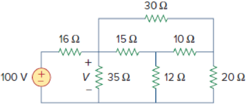
Figure 2.120
Calculate the value of voltage
Answer to Problem 56P
The value of voltage
Explanation of Solution
Formula used:
Consider the wye to delta conversions.
Here,
Consider the expression for
Here,
Consider the expression for
Calculation:
Refer to Figure 2.120 in the textbook For Prob.2.56.
Step 1:
From Figure 2.120, consider
Substitute
Substitute
Substitute
Modify Figure 2.120 as shown in Figure 1.
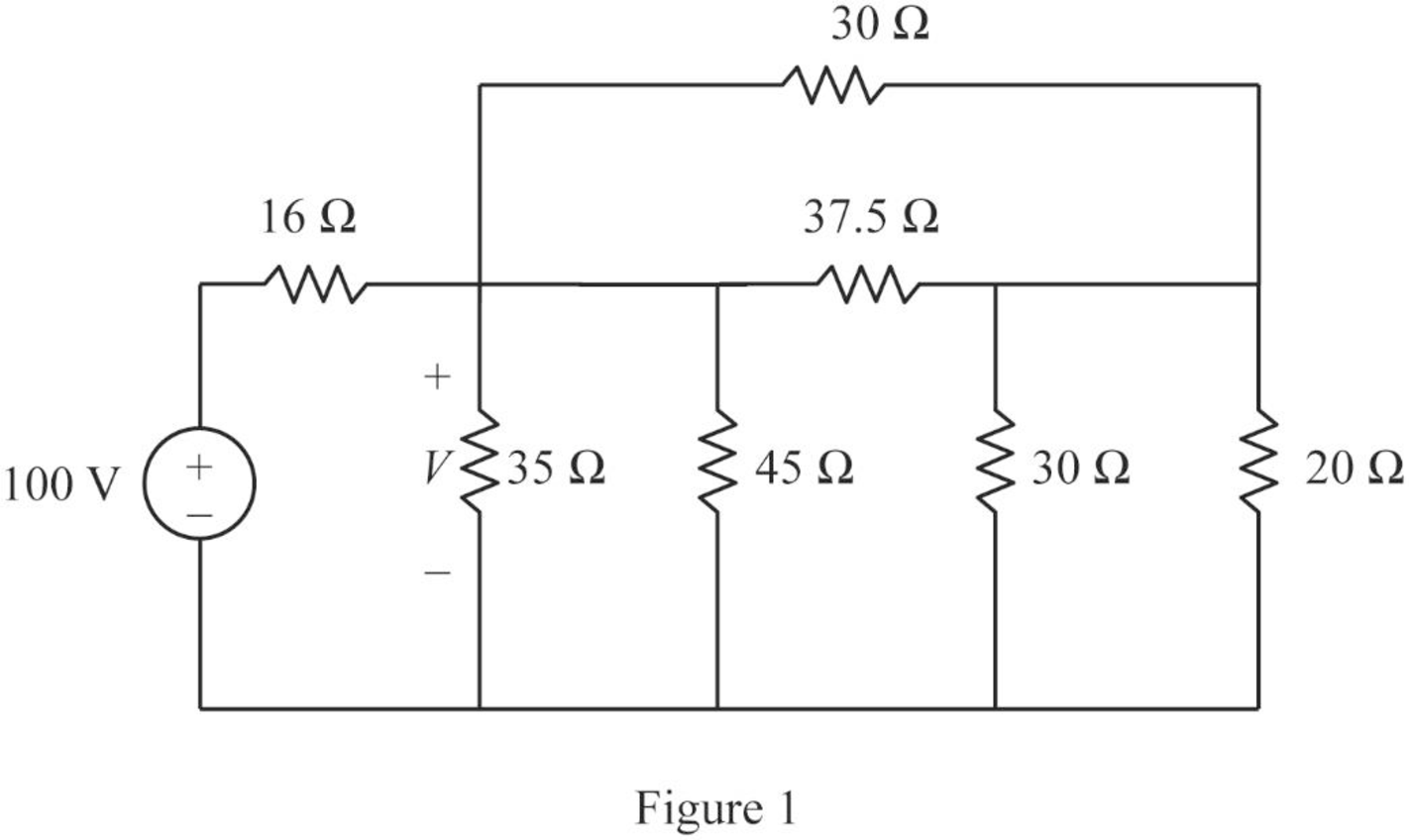
Step 2:
In Figure 1, as
Step 3:
In Figure 1, as
Step 4:
In Figure 1, as
Modify Figure 1 as shown in Figure 2.
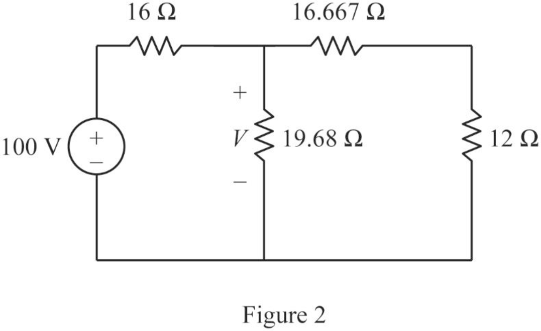
Step 5:
In Figure 2, as
Modify Figure 2 as shown in Figure 3.
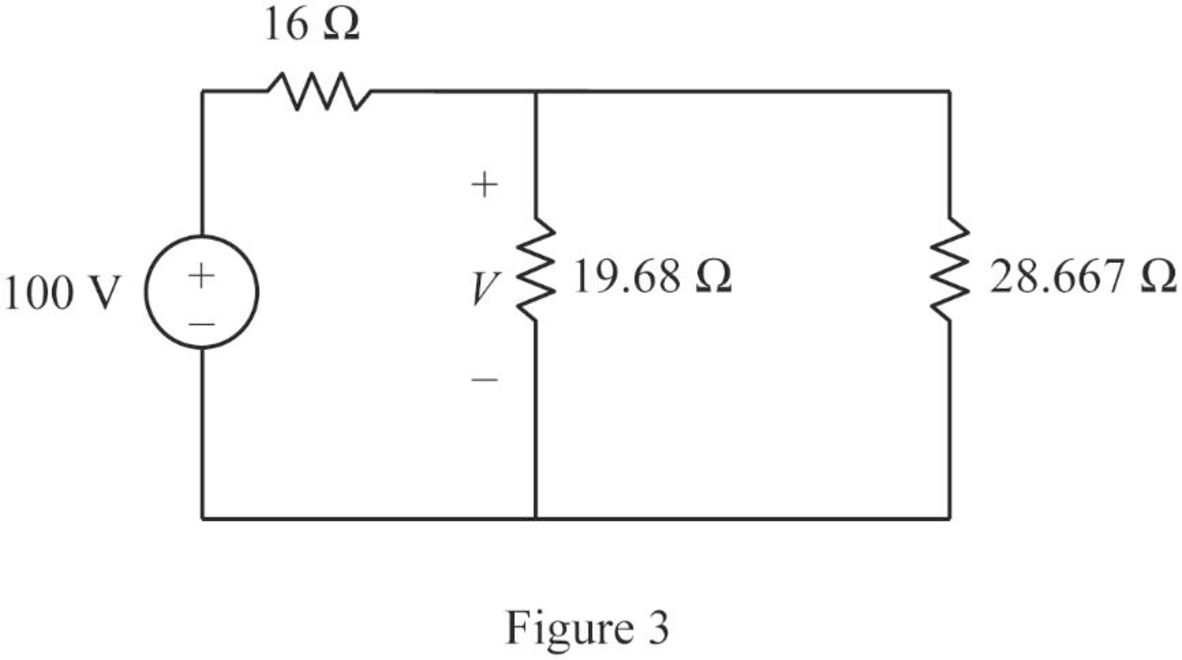
Step 6:
In Figure 3, as
Modify Figure 3 as shown in Figure 4.
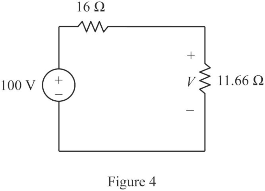
Step 7:
Apply voltage division rule to Figure 4.
Conclusion:
Thus, the value of voltage
Want to see more full solutions like this?
Chapter 2 Solutions
EBK FUNDAMENTALS OF ELECTRIC CIRCUITS


- Q3/A 8-pole, 3-phase, 50 Hz induction motor, running at 725 r.p.m, rotor is star connected its resistance and reactance 0.25 and 1.5 ohm per phase, the emf between slip rings is 100, find the rotor current per phase, power factor, synchronous speed, slip and rotor frequencyarrow_forward440 v, 4-pole, 3-phase, 50 Hz, star stator connected induction motor, full load speed 1425 r.p.m, rotor impedance 0.5+4.55ohm and rotor/stator ratio 0.8 calculate 1) starting torque, (2) rotor current (3) the value of external resistance to add to give maximum starting torque (4) power factor at maximum torque.arrow_forwardI would like to know the gear ratio and the tractive effort that a trolley must achieve with the following motor specifications: Voltage: 600 voltsSpeed: 1750 to 2300 RPMCurrent: 84 AmpsRated Power: 50-55 HP What percentage should be considered for gear efficiency, and what safe margin should be applied in these calculations? The constraints for the truck trolley are as follows:Maximum Speed: 50 MPHWeight of the Car Body: 46,000 lbs (the trolley weighs approximately 44,000 lbs)Diameter wheels: 86 inchesAdditionally, I would like to know how to plot a graph of tractive effort (in grams) versus speed (in MPH).arrow_forward
- A scientist proposed building an EM wave as E= 6000 sin (300 x -5000t) j + 6000 sin (300 x -5000t)k andB= -0.25 sin (300 x -5000t) i + 0.25 sin (300 x -5000t) k. Explain why this is not possible and explain all the mistakes E= 6000 sin (300 x -wt) j . Find the value for w and find the magnetic field vector and the Poynting vector as afunction of x and t.arrow_forwardSolve this problem and show all of the workarrow_forwardSolve this problem and show all of the workarrow_forward
- 2. A system with unity feedback is shown below. The feed-forward transfer function is G(s), where 5 . G(S) = (+1) Sketch the root locus for the variations in the values of pi. (s+P1)s R(s) C(s) G(s)arrow_forward3. The following closed-loop systems in Fig. 1 and Fig. 2 operate with a damping ratio of 0.707 (=0.707). The system in Fig. 1 does not have a PI controller, while the one in Fig. 2 does. R(s): S Gain Plant R(s) + E(s) 1 C(s) K (s+1)(s+2)(s+10) Fig. 1: Closed-loop system without PI controller Compensator Plant R(s) + E(s) K(s+0.1) S 1 (s+1)(s+2)(s+10) C(s) Fig. 2: Closed-loop system with a practical PI controller a. Please use Matlab to find the intersection point between line and the root locus of the system in Fig. 1. Then find the K value and one complex closed-loop pole corresponding to the intersection point. Calculate the steady-state error. Show the Matlab code in your answer sheet. b. Please use Matlab to find the intersection point between § line and the root locus of the system in Fig. 2. Then find the K value and one complex closed-loop pole associated with the intersection point. Compare the complex closed-loop pole with the one you just found in task a. Are they very…arrow_forward1. Please draw the root locus by hand for the following closed-loop system, where G(s) = s+6 = S-2 s+8 s-2' and H(s) = Find the range of K for stability using Method II in Examples 2 and 3 in Lecture 15. Input R(s) Output C(s) KG(s) H(s)arrow_forward
- 9-1) Lathi & Ding, Prob. P.5.1-10 (a) A first-order-hold circuit can also be used to reconstruct a signal g(t) from its samples. The impulse response of this circuit is h(t) = A ( 2Ts 12 where Ts is the sampling interval. Consider a typical sampled signal ğ(t) and show that this circuit performs the linear interpolation. In other words, the filter output consists of sample tops connected by straight-line segments. Follow the procedure discussed in Sec. 5.1.2 (Fig. 5.6) for a typical signal g(t). (b) Determine the transfer function of this filter and its amplitude response, and compare it with the ideal filter required for signal reconstruction.arrow_forwardI have this rough circuit diagram of a 2 double end trolley light system with a 120 dcv power supply. I would like to know in what way is better to connect the interior lights along with the headlight and door light. Provide the circuit diagram and with its respect connection and the estimated total power rated for the lights. Where: Headlights (2) = #1 and #6Door lights (4) = #2, #4, #5, and #7Platform lights (2) = #3 and #8Interior lights are approximately 20 in quantity. Also, can you say if the components that are in series with the power supply are correct or does it need to be replaced with something else or if it is missing any components.arrow_forwardA domestic load of 2300 kW at 0.88 p.f lagging and a motors load of 3400 kW at 0.85 p.f lagging are supplied by two alternators operating in parallel. If one alternator is delivering a load of 3300 kW at 0.9 p.f lagging, what will be the output power and p.f of the other alternator?arrow_forward
 Introductory Circuit Analysis (13th Edition)Electrical EngineeringISBN:9780133923605Author:Robert L. BoylestadPublisher:PEARSON
 Delmar's Standard Textbook Of ElectricityElectrical EngineeringISBN:9781337900348Author:Stephen L. HermanPublisher:Cengage Learning
 Programmable Logic ControllersElectrical EngineeringISBN:9780073373843Author:Frank D. PetruzellaPublisher:McGraw-Hill Education
 Fundamentals of Electric CircuitsElectrical EngineeringISBN:9780078028229Author:Charles K Alexander, Matthew SadikuPublisher:McGraw-Hill Education
 Electric Circuits. (11th Edition)Electrical EngineeringISBN:9780134746968Author:James W. Nilsson, Susan RiedelPublisher:PEARSON
 Engineering ElectromagneticsElectrical EngineeringISBN:9780078028151Author:Hayt, William H. (william Hart), Jr, BUCK, John A.Publisher:Mcgraw-hill Education,