
Concept explainers
Videos
Obtain the equivalent resistance Rab in each of the circuits of Fig. 2.117. In (b), all resistors have a value of 30 Ω.
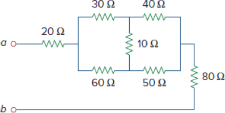
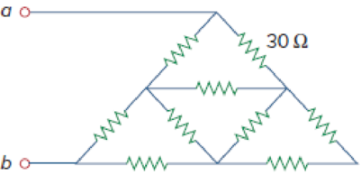
Figure 2.117
(a)
Calculate the equivalent resistor at terminals a-b in Figure 2.117(a).
Answer to Problem 53P
The equivalent resistor at terminals a-b in Figure 2.117(a) is
Explanation of Solution
Formula used:
Consider the delta to wye conversions.
Here,
Consider the expression for
Here,
Consider the expression for
Calculation:
Refer to Figure 2.117(a) in the textbook For Prob.2.53.
Step 1:
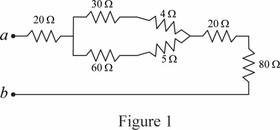
In Figure 2.117(a), convert the delta connection into wye connection.
Consider
Substitute
Substitute
Substitute
Modify Figure 2.117(a) as shown in Figure 1.
Step 2:
In Figure 1, as
Step 3:
In Figure 1, as
Step 4:
In Figure 1, as
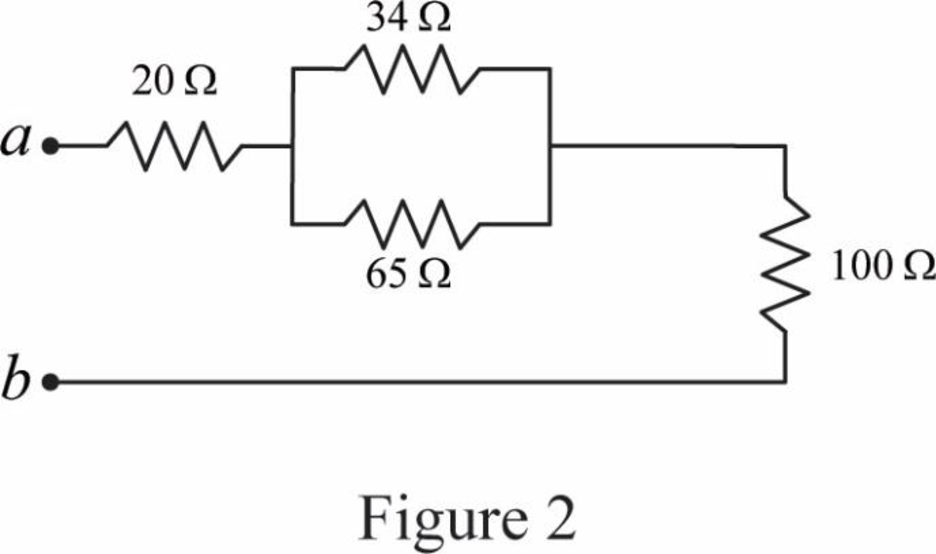
Modify Figure 1 as shown in Figure 2.
Step 5:
In Figure 2, as
Modify Figure 2 as shown in Figure 3.
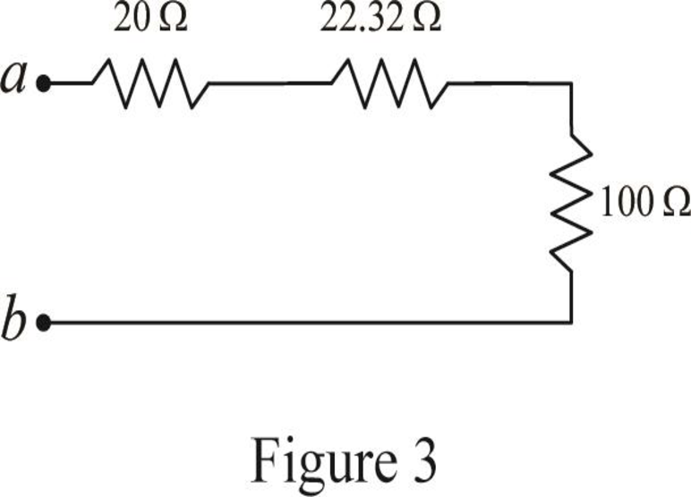
Step 6:
In Figure 3, as
Conclusion:
Thus, the equivalent resistor at terminals a-b in Figure 2.117(a) is
(b)
Calculate the equivalent resistor at terminals a-b in Figure 2.117(b).
Answer to Problem 53P
The equivalent resistor at terminals a-b in Figure 2.117(b) is
Explanation of Solution
Given data:
All resistance have
Formula used:
Consider the following delta to wye conversion, when all branches in a delta consist same value.
Calculation:
Refer to Figure 2.117(b) in the textbook For Prob.2.53.
Step 1:
In Figure 2.117(b), at left most corner of circuit, as two resistors are connected in series, therefore the equivalent resistance for series connected circuit is calculated as follows.
Step 2:
As
Modify Figure 2.117(b) as shown in Figure 4.
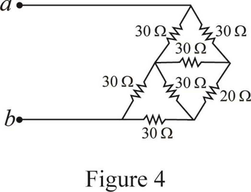
Step 3:
In Figure 4, as in upper part of the circuit all three
Substitute
Since all branch values are same in a delta connection that is
Modify Figure 4 as shown in Figure 5.
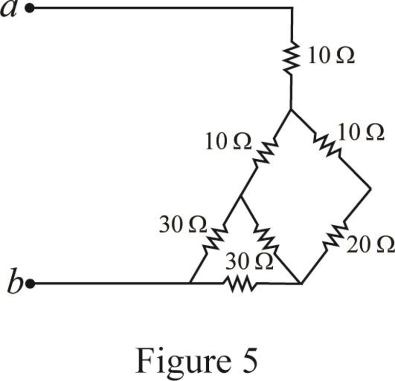
Step 4:
In Figure 5, as
Step 5:
In Figure 5, as in right most part of the circuit all three
Substitute
Since all branch values are same in a delta connection that is
Modify Figure 5 as shown in Figure 6.
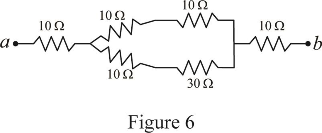
Step 6:
In Figure 6, as
Step 7:
In Figure 6, as
Step 8:
As
Modify Figure 6 as shown in Figure 7.
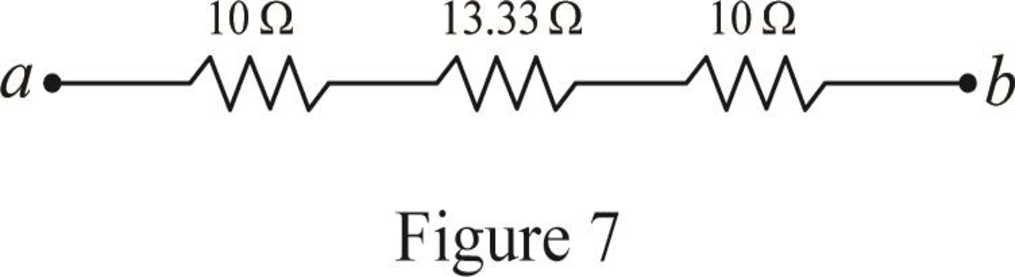
Step 4:
In Figure 7, as
Conclusion:
Thus, the equivalent resistor at terminals a-b in Figure 2.117(b) is
Want to see more full solutions like this?
Chapter 2 Solutions
EBK FUNDAMENTALS OF ELECTRIC CIRCUITS
Additional Engineering Textbook Solutions
Modern Database Management
Mechanics of Materials (10th Edition)
Starting Out With Visual Basic (8th Edition)
Vector Mechanics for Engineers: Statics and Dynamics
Database Concepts (8th Edition)
Electric Circuits. (11th Edition)


- 1. The communication channel bandwidth is 25 MHz centered at 1GHz and has a noise power spectral density of 10^-9 W/Hz. The channel loss between the transmitter and receiver is 25dB. The application requires a bit rate of 200Mbps and BER of less than 10^-4. Excluding Mary FSK, Determine the minimum transmit power required.arrow_forward2. An existing system uses noncoherent BASK. The application requires a BER of <10^-5. The current transmit power is 25 Watts. If the system changes to a coherent BPSK modulation scheme, what is the new transmit power required to deliver the same BER?arrow_forward3. You are to design a 9-volt battery operated communication system that must last 3 years without replacing batteries. The communication channel bandwidth is 100 KHz centered at 5.8 GHz. The application requires a BER of <10^-5 and a data rate of 1 Mbps. The channel can be modeled as AWGN with a noise power spectral density of 10^-8 W/Hz. ((a) What modulation scheme would you use? B) what is the required capacity of the batteries? and (c) is the battery commercially available?arrow_forward
- Design a traffic light PIC microcontroller program with Green LED has 3 Sec Yellow LED has 0.5 Sec Red LED has 3 Sec RASAN4SSC20UT 8 RBOINT RB1 9 RB2 U1 PIC16F877A-I/PT 18 19 MCLRVPP RAOANO 20 RA1AN1 30 OSCICLKI 21 RAZAN2VREF-CVREF 31 OSC2CLKO RABAN3VREF+ 22 LED1 LED-3MM 〃 R1 330 RA4TOCKIC1OUT 23 7 VDD 28 VDD 6 VSS 29 VSS 24 LED2 LED-3MM R2 10 330 RB3PGM 11 + 14 RB4 38 RDOPSPO RB5 15 LED3 39 RD1PSP1 40 RD2PSP2 RB6PGC- RB7PGD 17 16 LED-3MM R3 330 41 RD3PSP3 2 RD4PSP4 RCOT1OSOTICKK 3 RDSPSPS RC1T10SICCP24 RD6PSP6 RC2CCP1 5 RD7PSP7 RC3SCKSCL RC4SDISDA 25 REORDANS RCSSDO 27 29 REIWRANG RC6TXCK- RE2CSAN7 RC7RXDT DAWWWW 32 35 36 37 42 43 44 1 12 NO 13 NC 33 NO 34 NCarrow_forward: +0 العنوان I need a detailed drawing with explanation しじ ined sove in peaper Anoting Q4// Draw and Evaluate √√√xy-²sin(y²)dydx PU+96er Lake Ge Q3// Find the volume of the region between the cylinder 2 = y² and the xy- plane that is bounded by the planes x = 1, x = 2, y = -2, and y = 2. T Marrow_forwardFind Va and Vb using Mesh analysisarrow_forward
- Please solve this question step by step and handwritten and do not use chat gpt or ai tools thank you very much!arrow_forwardPlease solve question c and d step by step and handwritten and do not use chat gpt or ai tools thank you very much!arrow_forwardPlease solve questions d,e,f step by step and handwritten and do not use chat gpt or ai tools thank you very much!arrow_forward
 Introductory Circuit Analysis (13th Edition)Electrical EngineeringISBN:9780133923605Author:Robert L. BoylestadPublisher:PEARSON
 Delmar's Standard Textbook Of ElectricityElectrical EngineeringISBN:9781337900348Author:Stephen L. HermanPublisher:Cengage Learning
 Programmable Logic ControllersElectrical EngineeringISBN:9780073373843Author:Frank D. PetruzellaPublisher:McGraw-Hill Education
 Fundamentals of Electric CircuitsElectrical EngineeringISBN:9780078028229Author:Charles K Alexander, Matthew SadikuPublisher:McGraw-Hill Education
 Electric Circuits. (11th Edition)Electrical EngineeringISBN:9780134746968Author:James W. Nilsson, Susan RiedelPublisher:PEARSON
 Engineering ElectromagneticsElectrical EngineeringISBN:9780078028151Author:Hayt, William H. (william Hart), Jr, BUCK, John A.Publisher:Mcgraw-hill Education,