Concept explainers
Videos
(a)
The couple
Answer to Problem 18.102P
The couple
Explanation of Solution
Given information:
Angular velocity of disk in z-direction is
The figure is represented below.
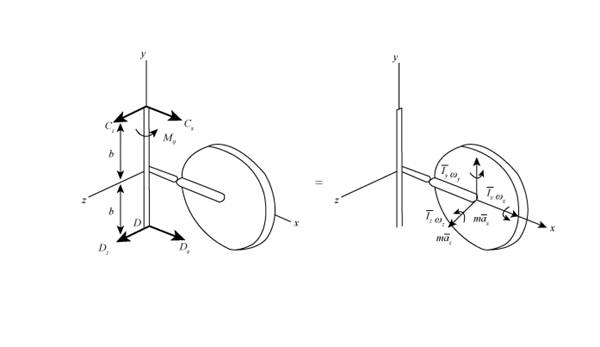
Figure (1)
Write the equation for the mass of the disk.
Here, weight of disk is
Write the expression for the angular momentum about point
Here, mass moment of inertia about the x-axis is
Write the expression for the angular velocity of disk in x direction.
Substitute
Here,
Write the expression for angular velocity in vector form.
Write the expression for rate of angular velocity of the reference frame
Write the expression for rate of total angular velocity.
Substitute
Write the expression for Matrix multiplication of the vector product for Equation (8).
Write the expression for the mass moment of inertia about the y-direction.
Here mass of the disk is
Write the expression for the mass moment of inertia about the z- direction.
Substitute
Write the expression for the velocity of mass centre of the disk.
Here, velocity of mass centre is
Write the expression for the matrix multiplication of the vector product for Equation (13).
Write the expression for the acceleration of the mass centre of the disk.
Write the expression for the matrix multiplication of the vector product for Equation (15).
Write the expression for the the sum of the forces acting on the system.
Write the expression for the force in terms of mass and acceleration.
Substitute
Here, force at
Substitute
Compare the coefficients of the unit vector of
Compare the coefficients of the unit vector of
Write the expression for the rate of angular momentum about
Here, distance between
Write the expression for
Here, distance from the centre of disk to point
Substitute
Write the expression for the matrix multiplication for vector product for equation (24).
Write the expression for the moment about
Here, length of
Write the expression for the matrix multiplication for the vector product for equation (26).
Here
The sum of the moment at
Substitute
Compare the coefficients of the unit vector of
Compare the coefficients of the unit vector of
Compare the coefficients of the unit vector of
Substitute
Substitute
Calculation:
Substitute
Substitute values of
Thus value of couple
Conclusion:
The value of couple is
(b)
The dynamic reaction at
The dynamic reaction at
Answer to Problem 18.102P
The dynamic reaction at
The dynamic reaction at
Explanation of Solution
Given information:
Write the expression for the angular velocity in terms of time in y-direction.
Here time is
Calculation:
Substitute
Substitute values of
Substitute values of
Hence, dynamic reaction at
Substitute values of
Substitute values of
Hence, dynamic reaction at
Conclusion:
The dynamic reactions at
The dynamic reactions at
Want to see more full solutions like this?
Chapter 18 Solutions
VECTOR MECH...,DYNAMICS(LOOSE)-W/ACCESS


- d Q.2. A Pelton wheel has a mean bucket speed of 15 m/s. The jet of water issued from a nozzle of 12 cm in diameter impinges the bucket with a velocity of 40 m/s. If the buckets deflect the jet through an angle of 165°, find the head and power generated by the turbine. Assume the hydraulic efficiency is 90% and the mechanical efficiency is 85%. [50 Marks] Po 7n = 90%arrow_forwardAt its optimum point of caines. operation, a given centrifugal pump with an impeller diameter of 50 cm delivers 3.2 m³/s of water at a 2 head of 25 m when rotating at 1450 rpm and power of 955 kW. If a homologous pump with an impeller diameter of 80 cm rotates at 1200 rpm, what would be the discharge, head, shaft break power and P H₂arrow_forward(read image)arrow_forward
- Hi, can you please assist with the attached question please. Please do not use Ai software. Many thanks.arrow_forwarddetermine the allowable bending and contact stresses for a grade 1 steel through-hardened to 250 HB. Assume the desired reliability is 50% and that the pinion and gear have the same hardness and the gear encounters hydrodynamic lubrication and is to last ten million cyclesarrow_forwardUsing the four-point bending tool, detail the influence of both applied load and notch size on the transverse strain. Cover the following points in your answer. a. A detailed description of the methodology you have used to create a set of results suitable to answer this question. Include details on the placement of line scans, the loads used, etc. (there is no need to describe the process of extracting the data from the interactive or the fundamental principles behind DIC). (5 marks) b. A description of the results you have found, including a written description, images, and both vertical and horizontal line scans from the four-point bending tool. Include a minimum of three loads and three notch sizes in your results. (20 marks) c. The conclusions you can make regarding the influence of load and notch size on the strain experienced by the beam based on the data you collect. (5 marks) To achieve full marks, you will need to include the following in your work: • properly labelled graphs…arrow_forward
- Using the four-point bending tool, discuss how measurements of transverse strain using DIC and compare with those from the strain gauge attached at the centre top of the specimen. In your answer, include the following: a. A short explanation of how each of the strain measurement techniques works. (4 marks) b. A description of the methodology you have used to make the data that you discussed from each technique as comparable as possible. (6 marks) c. A set of figures (images, graphs and/or tables as necessary) with appropriate captions demonstrating the comparability of data extracted from the two strain measurement methods. This should include at least three different applied loads. (10 marks) d. A brief description of the findings. (5 marks)arrow_forwardAn undamped single-degree-of-freedom system consists of a spring with stiffness k = 10 kip/in and a mass weighing W = 10 kips. The system is at rest and it is suddenly subjected to a half-cycle sine pulse force. The pulse force has an amplitude po = 1 kips and time duration td = 0.1 seconds. Calculate the maximum restoring force in the spring due to the pulse force.arrow_forwardm=400mm n=300mm q=28mm r=20mm P=0.9kNarrow_forward
- determine the allowable bending and contact stresses for a Grade 1 steel through-hardened to 250 HB. Assume the desired reliability is 50 %and that the pinion and gear have the same hardness and it is expected that the gear will encounter 100,000 load cyclesarrow_forwardPlease can you plot the Mohr's strain circle using the above informarrow_forwardA gearbox has permanent shaft positions defined by the bearing mounting positions, but the gear ratio can be changed by changing the number of teeth in the pinion and gear. To achieve similar power transmission ability for different gear ratios, a manufacturer chooses to have the same module for two different gearboxes. One of the gaerboxes has a pinion with 22 teeth, a gear with 68 teeth, and a center distance of 225mm. How large is the gear module and which gear ratios are possible for a pinion with 22 or more teeth using the same module?arrow_forward
 Elements Of ElectromagneticsMechanical EngineeringISBN:9780190698614Author:Sadiku, Matthew N. O.Publisher:Oxford University Press
 Mechanics of Materials (10th Edition)Mechanical EngineeringISBN:9780134319650Author:Russell C. HibbelerPublisher:PEARSON
 Thermodynamics: An Engineering ApproachMechanical EngineeringISBN:9781259822674Author:Yunus A. Cengel Dr., Michael A. BolesPublisher:McGraw-Hill Education
 Control Systems EngineeringMechanical EngineeringISBN:9781118170519Author:Norman S. NisePublisher:WILEY
 Mechanics of Materials (MindTap Course List)Mechanical EngineeringISBN:9781337093347Author:Barry J. Goodno, James M. GerePublisher:Cengage Learning
 Engineering Mechanics: StaticsMechanical EngineeringISBN:9781118807330Author:James L. Meriam, L. G. Kraige, J. N. BoltonPublisher:WILEY