
Concept explainers
Videos
(a)
The couple
Answer to Problem 18.77P
The couple
Explanation of Solution
Given information:
The total mass is
Write the expression for the sum of the moment acting on the body along x -direction.
Here, the product of the moment of the inertia of
Write the expression for the sum of the moment acting on the body along y -direction.
Write the expression for the sum of the moment acting on the body along z -direction.
Here, the moment of the inertia along the z -direction is
Draw the diagram for the for the sheet metal component.
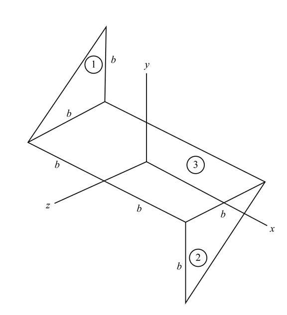
Figure-(1)
Write the expression for the area of the section 1 shown in the Figure-(1).
Here, the constant dimension is
Write the expression for the area of the section 2 shown in the Figure-(1).
Write the expression for the area of the section 3 shown in the Figure-(1).
Write the expression for the total area of the sheet.
Substitute
Write the expression of mass per unit area of the system.
Here, the mass of the sheet metal component is
Write the expression for the variation of the
Here, the coordinate of the considered point is
The below figure represent the schematic diagram of the elemental strip of section 1.
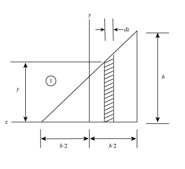
Figure-(2)
Write the expression for the distance of the centroid of the element from the
Write the expression for the mass of the elemental strip.
Here, the area of the elemental strip is
Write the expression for the moment of inertia of the element with respect to z- axis.
Write the expression for the moment of the inertia of the section 1.
Write the expression for the product of moment of inertia of the plane
Write the expression for the product of moment of inertia of the plane
Write the expression for the variation of the
The below figure represent the schematic diagram of the elemental strip of section 2.
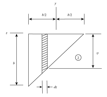
Figure-(3)
Write the expression for the mass of the elemental strip of section 2.
Write the expression for the moment of the inertia of the section 2.
Write the expression for the product of moment of inertia of the plane
Write the expression for the product of moment of inertia of the plane
Write the expression of mass per unit area of the section3 in Figure-(1).
Here, the mass of the rectangular sheet metal component is
Write the expression for the moment of the inertia of the section 3.
The product moment of the inertia for the plane
Write the expression for the moment of the inertia of the whole system.
Write the expression for the product of moment of inertia of the whole system.
Write the expression for the product of moment of inertia of the whole system.
Draw the diagram for the system to shows the action of forces on the system.
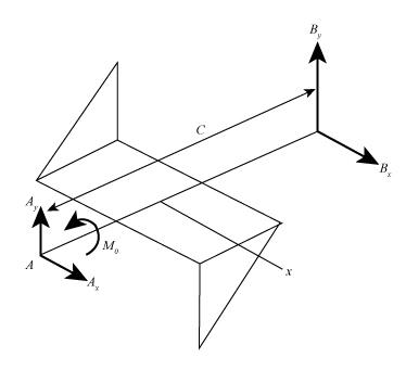
Figure-(4)
Here, the reaction on the point
Calculation:
Substitute
Substitute
Substitute
Substitute
Substitute
Substitute
Substitute
Substitute
Substitute
Conclusion:
The couple
(b)
The dynamic reactions at
The dynamic reactions at
Answer to Problem 18.77P
The dynamic reactions at
The dynamic reactions at
Explanation of Solution
Write the expression for the dynamic reaction at point
Write the expression for the dynamic reaction at point
Write the expression for the reaction forces along the y- direction.
Write the expression for the reaction forces along the x- direction.
Write the expression for the sum of the moment acting on the body along x -direction.
Here, distance between the point
Write the expression for the sum of the moment acting on the body along y -direction.
Calculation:
Substitute
Substitute
Substitute
Substitute
Substitute
Substitute
Substitute
Substitute
Substitute
Substitute
Substitute
Substitute
Substitute
Substitute
Conclusion:
The dynamic reactions at
The dynamic reactions at
Want to see more full solutions like this?
Chapter 18 Solutions
VECTOR MECH...,DYNAMICS(LOOSE)-W/ACCESS


- The answer is not 0.293 marrow_forwardplease first help me solve this problem find the line of action and them help to find the forces like for example {fx= fy= mz= and determine the shear force in the nailsarrow_forwardAn open channel of square cross section had a flowrate of 17.2 ft³/s when first used. After extended use, the channel became 0.6-filled with silt. Determine the flowrate for this silted condition. Assume the Manning coefficient is the same for all the surfaces. Qs= ! ft³/sarrow_forward
- (Manning equation) The triangular flume shown in the figure below is built to carry its design flowrate, Qo, at a depth of 0.991 m as is indicated. If the flume is to be able to carry up to twice its design flowrate, Q = 2Qo, determine the freeboard, I, needed. ✓ -90°- 0.991 m i marrow_forwardWater flows in a 2-ft-wide rectangular channel at a rate of 10 ft³/s. If the water depth downstream of a hydraulic jump is 2.5 ft, determine (a) the water depth upstream of the jump, (b) the upstream and (c) downstream Froude numbers, and (d) the head loss across the jump. (a) y₁ = i (b) Fr₁ = i (c) Fr₂ = i (d) h₁ = ft ftarrow_forwardA hydraulic jump at the base of a spillway of a dam is such that the depths upstream and downstream of the jump are 0.8 and 3.2 m, respectively (see the Video). If the spillway is 12 m wide, what is the flowrate over the spillway? Q= i m³/sarrow_forward
- (Manning equation) Water flows in a rectangular channel of width b at a depth of b/2. Determine the diameter of a circular channel (in terms of b) that carries the same flowrate when it is half-full. Both channels have the same Manning coefficient, n, and slope. barrow_forward(Manning equation) A weedy irrigation canal of trapezoidal cross section is to carry 20 m³/s when built on a slope of 0.60 m/km. If the sides are at a 45° angle and the bottom is 8 m wide, determine the width of the waterline at the free surface. i marrow_forwardWater flows in a 1.2-m-diameter finished concrete pipe so that it is completely full and the pressure is constant all along the pipe. If the slope is So = 0.0073, (a) determine the flowrate by using open-channel flow methods. Compare this result with (b) that obtained using the pipe flow methods of Chapter 8 (Use Colebrook formula, Table 8.1, Table 10.1 and assume that Re > 10º). (a) Q = i (b) Q = i m³/s m³/sarrow_forward
- for this 4 figuredarw the Kinematic Diagram:DoF:F=Type/Name ofmechanismEvolution:arrow_forwardTwo channels and two plates are used to formthe column section shown. For b = 200 mm,determine the moments of inertia and theradii of gyration of the combined section withrespect to the centroidal x and y axes.For the section of problem, determine thefirst moment of the upper plate about thecentroidal x-axisarrow_forwardDetermine by direct integration the moment of inertia of theshaded area at right with respect to the x axis shown. Determine by direct integration the moment of inertia of theshaded area of the figure with respect to the y axis shown.arrow_forward
 Elements Of ElectromagneticsMechanical EngineeringISBN:9780190698614Author:Sadiku, Matthew N. O.Publisher:Oxford University Press
 Mechanics of Materials (10th Edition)Mechanical EngineeringISBN:9780134319650Author:Russell C. HibbelerPublisher:PEARSON
 Thermodynamics: An Engineering ApproachMechanical EngineeringISBN:9781259822674Author:Yunus A. Cengel Dr., Michael A. BolesPublisher:McGraw-Hill Education
 Control Systems EngineeringMechanical EngineeringISBN:9781118170519Author:Norman S. NisePublisher:WILEY
 Mechanics of Materials (MindTap Course List)Mechanical EngineeringISBN:9781337093347Author:Barry J. Goodno, James M. GerePublisher:Cengage Learning
 Engineering Mechanics: StaticsMechanical EngineeringISBN:9781118807330Author:James L. Meriam, L. G. Kraige, J. N. BoltonPublisher:WILEY