
Concept explainers
Videos
Solve Prob. 18.129, assuming that the meteorite hits the satellite at A instead of B.
The precession angles.
The rate of precession of the satellite after the impact.
The rate of spin axis of the satellite after the impact.
Answer to Problem 18.130P
Thus, the precession angle about the x-axis, y-axis, and z-axis are
The rate of precession of the satellite after impact is
The rate of spin axis of the satellite after impact is
Explanation of Solution
Given information:
The weight of the geostationary satellite is
Write the expression of the mass of the meteorite.
Here, the weight of the meteorite is
Write the expression of the mass of the satellite.
Here, weight of the meteorite is
Write the Expression of the moment of inertia along x-axis.
Here, the radius of gyration of the satellite along x-axis is
Write the Expression of the moment of inertia along the y-axis.
Here, the radius of gyration of the satellite along y-axis is
Write the Expression of the moment of inertia along z-axis.
Here, the radius of gyration of the satellite along z-axis is
Write the expression of the initial momentum of the meteorite.
Here, the initial velocity of the meteorite is
Write the expression of initial angular momentum of the satellite before the impact.
Here, the initial angular velocity along x-axis is
Write the expression of the angular momentum about point A before impact.
Here, the distance between point A, and
Write the expression of angular momentum of the satellite after impact.
Here, the angular velocity after impact along x-axis is
According to the momentum equilibrium, the angular momentum before and after the impact of meteorite at point A will be same.
Write the expression of magnitude net angular velocity after impact of meteorite.
Write the expression of magnitude net angular momentum after impact of meteorite.
The satellite is symmetrical about y-axis.
Write the expression of moment of inertia along the symmetry axis.
Figure-(1) shows the precession axis and the spin axis.
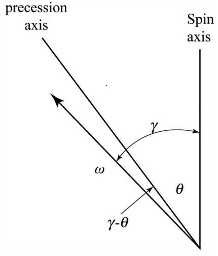
Figure-(1)
Here, angle of precession axis with respect to x, y and z axes is defined in cosine, the angular velocity is
Write the expression of the angle of precession axis with respect to x-axis.
Here, the angle of precession axis with respect to x-axis is
Write the expression of the angle of precession axis with respect to y-axis.
Here, the angle of precession axis with respect to x-axis is
Write the expression of the angle of precession axis with respect to y-axis.
Here, the angle of precession axis with respect to x-axis is
Figure-(2) shows the angle of spin axis with respect to precession axis is constant.
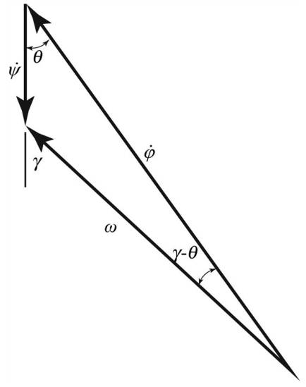
Figure-(2)
Here, the rate of precession is
Write the expression of the angle of precession axis with respect to spin axis is constant from figure (2).
Write the expression of the angle of angular velocity with respect to spin axis.
Here, the angle of angular velocity with respect to spin axis is
Write the expression for relation between
Calculation:
Substitute
Substitute
Substitute
Substitute
Substitute
Substitute in
Substitute
Substitute
Substitute
Equate x-components in Equation (XIX) on both side and substitute
Equate y-components in Equation (XIX) on both side and substitute
Equate z-components in Equation (XIX) on both side and substitute
Substitute
Substitute
Substitute
Substitute
Substitute
Substitute
Substitute
Compare first and second term of Equation (XVIII).
Substitute
Compare second and third term of Equation (XVIII).
Substitute
Conclusion:
Thus, the precession angle about the x-axis, y-axis, and z-axis are
The rate of precession of the satellite after impact is
The rate of spin axis of the satellite after impact is
Want to see more full solutions like this?
Chapter 18 Solutions
VECTOR MECH...,DYNAMICS(LOOSE)-W/ACCESS


- (read image) (answer given)arrow_forward11-5. Compute all the dimensional changes for the steel bar when subjected to the loads shown. The proportional limit of the steel is 230 MPa. 265 kN 100 mm 600 kN 25 mm thickness X Z 600 kN 450 mm E=207×103 MPa; μ= 0.25 265 kNarrow_forwardT₁ F Rd = 0.2 m md = 2 kg T₂ Tz1 Rc = 0.4 m mc = 5 kg m = 3 kgarrow_forward
- 2. Find a basis of solutions by the Frobenius method. Try to identify the series as expansions of known functions. (x + 2)²y" + (x + 2)y' - y = 0 ; Hint: Let: z = x+2arrow_forward1. Find a power series solution in powers of x. y" - y' + x²y = 0arrow_forward3. Find a basis of solutions by the Frobenius method. Try to identify the series as expansions of known functions. 8x2y" +10xy' + (x 1)y = 0 -arrow_forward
- Hello I was going over the solution for this probem and I'm a bit confused on the last part. Can you please explain to me 1^4 was used for the Co of the tubular cross section? Thank you!arrow_forwardBlood (HD = 0.45 in large diameter tubes) is forced through hollow fiber tubes that are 20 µm in diameter.Equating the volumetric flowrate expressions from (1) assuming marginal zone theory and (2) using an apparentviscosity for the blood, estimate the marginal zone thickness at this diameter. The viscosity of plasma is 1.2 cParrow_forwardQ2: Find the shear load on bolt A for the connection shown in Figure 2. Dimensions are in mm Fig. 2 24 0-0 0-0 A 180kN (10 Markarrow_forward
- determine the direction and magnitude of angular velocity ω3 of link CD in the four-bar linkage using the relative velocity graphical methodarrow_forwardFour-bar linkage mechanism, AB=40mm, BC=60mm, CD=70mm, AD=80mm, =60°, w1=10rad/s. Determine the direction and magnitude of w3 using relative motion graphical method. A B 2 3 77777 477777arrow_forwardFour-bar linkage mechanism, AB=40mm, BC=60mm, CD=70mm, AD=80mm, =60°, w1=10rad/s. Determine the direction and magnitude of w3 using relative motion graphical method. A B 2 3 77777 477777arrow_forward
 Elements Of ElectromagneticsMechanical EngineeringISBN:9780190698614Author:Sadiku, Matthew N. O.Publisher:Oxford University Press
 Mechanics of Materials (10th Edition)Mechanical EngineeringISBN:9780134319650Author:Russell C. HibbelerPublisher:PEARSON
 Thermodynamics: An Engineering ApproachMechanical EngineeringISBN:9781259822674Author:Yunus A. Cengel Dr., Michael A. BolesPublisher:McGraw-Hill Education
 Control Systems EngineeringMechanical EngineeringISBN:9781118170519Author:Norman S. NisePublisher:WILEY
 Mechanics of Materials (MindTap Course List)Mechanical EngineeringISBN:9781337093347Author:Barry J. Goodno, James M. GerePublisher:Cengage Learning
 Engineering Mechanics: StaticsMechanical EngineeringISBN:9781118807330Author:James L. Meriam, L. G. Kraige, J. N. BoltonPublisher:WILEY